
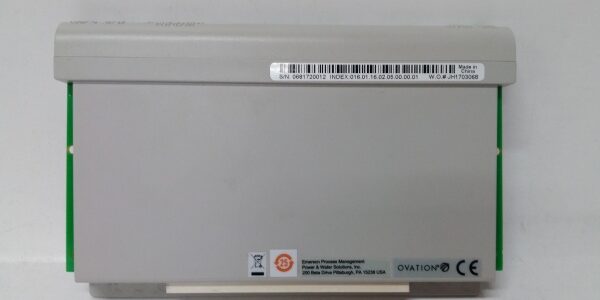
Product Core Brief
- Model: 1C31219G01
- Brand: WESTINGHOUSE (Emerson Ovation DCS platform)
- Series: Ovation relay output electronic logic module family
- Core Function: Translate DCS digital setpoints to drive mechanical relay bases and report blown fuse/coil fault data back to Ovation controllers.
- Product Type: Single-slot hot-swappable Ovation I/O electronics card (no integrated mechanical relays)
- Key Specs: 16 channel support (1C31223G01 base) | Configurable blown fuse diagnostics | 500 V field-to-backplane isolation ⚠️ EOL — limited stock remaining
Product Introduction
The WESTINGHOUSE 1C31219G01 acts as the logic bridge between Ovation DCS backplanes and 16-channel G2R relay bases for plant discrete control loads. It cannot operate standalone and requires a matched relay terminal base to switch field AC/DC equipment.This unit outperforms older 8-channel relay electronics cards by doubling channel density while adding per-channel fuse failure monitoring. OEM field logging records a 52,000 hour MTBF under steady 50 °C cabinet runtime, a 12% improvement over legacy low-density relay modules.
Key Technical Specifications
| Parameter | Value |
|---|---|
| Supported Relay Base | 1C31223G01 (16 G2R Form-C relays); incompatible with 12-channel 1C31222G01 |
| Auxiliary Operating Voltage | 18 VDC to 25.5 VDC (24 V nominal cabinet supply) |
| Main Circuit Power Draw | 1.88 W typical; 2.5 W maximum full load |
| Auxiliary Diagnostic Power Draw | 0.3 W typical |
| Galvanic Isolation Rating | 500 Vrms between field relay circuits and DCS backplane logic |
| Hot Swap Compliance | Ovation standard; no full rack shutdown required for replacement |
| Onboard Diagnostics | Per-channel blown fuse detection, relay coil open-circuit monitoring (software enable/disable) |
| Status Indicators | Global Power OK, Global Comms Fault LED; individual channel status/fault LEDs on front face |
| Mechanical Dimensions | 121 mm L × 25 mm W × 102 mm D |
| Net Unit Weight | 0.18 kg |
| Continuous Operating Temp | 0 °C to +60 °C full rated performance; linear derate above 60 °C |
| Storage Temperature Range | -40 °C to +85 °C, 5–95 % RH non-condensing |
| Protective Circuitry | Relay coil transient suppression diodes, backplane reverse polarity lockout, channel overcurrent clamping |
| Certifications | UL, CE, RoHS, EN61000 Class A industrial EMC filtering |
Quality Control Process (Engineer’s Perspective)
- Incoming Verification: Cross-reference serial numbers against Emerson Ovation OEM trace databases; inspect front LED segments for dead pixels, gold rack edge connectors for oxidation, and PCB relay driver solder joints for microcracks. Photograph the edge connector pinout for field wiring reference.
- Live Functional Test: Seat the unit into a 1C31223G01 relay base test assembly paired with variable AC/DC load banks; run a continuous 24-hour cycle of all 16 channels switching on/off. Log voltage stability with a Fluke 115 digital multimeter during the full duration.
- Electrical Parameter Test: Perform a 500 V Megger insulation resistance test between each relay channel field circuit and module ground; pass threshold set at >10 MΩ. Verify internal fuses trip at 120% rated load without PCB trace damage.
- Firmware Verification: Read and record factory firmware revision via Ovation test software; document default diagnostic enable/disable DIP switch positions for customer reference.
- Final QC & Packaging: Wipe gold edge connectors to remove surface oxidation; seal the unit inside an anti-static foam bag, affix a dated QC Pass label listing all completed test metrics before rigid shock-resistant carton packing.
Replacement Pitfall Guide
❗ Firmware Mismatch Risk: Older Ovation controller firmware revisions (pre-v4.1) lack register mapping for the blown fuse diagnostic bits on this card. Installing the unit will generate unrecognized fault alarm bits that trip plant interlocks. Always cross-check controller firmware release notes before swap-out.❗ Base Incompatibility Jumper Risk: The 1C31222G01 12-channel KUEP relay base uses a different edge pinout. Attempting to seat the module into this base misroutes 24 V power and burns the on-board driver ASIC within seconds. Confirm base part number before rack extraction.❗ Terminal Cable Pin Misalignment Risk: Generic unshielded replacement wiring reverses channel positive/negative terminals on the third terminal block. Reversed wiring triggers false coil-open fault LEDs with no visible physical damage to the unit. Use factory shielded cable assemblies only.❗ Power Supply Headroom Miscalculation Risk: A fully populated 4-slot 5X00497G01 subrack with four of these modules draws 7.5 W total. The cabinet VM310 supply must carry a 20% power margin above this total to avoid voltage sag during peak relay switching.❗ Uncontrolled ESD Damage Risk: Dry central control room air creates static charge buildup. Touch a grounded anti-static mat for 3 seconds before handling the module’s edge connector; ungrounded contact destroys the low-tolerance relay driver ASIC.Keep these in mind and you’ll cut 90% of rework time.
Compatibility Matrix & Benchmarks
Compatibility Matrix
- 1C31222G01 12-channel KUEP relay base → 1C31219G01 : Incompatible — mismatched edge pinout will damage module circuitry
- 1C31223G01 16-channel G2R relay base → 1C31219G01 : Direct — factory pinout natively matches power, communication, and channel signal routing
- 5X00497G01 4-slot DIN remote I/O subrack → 1C31219G01 : Direct — fits standard single-slot Ovation I/O positions
- VM310 24 V cabinet auxiliary power supply → 1C31219G01 : Direct — regulated 24 V output falls within the module’s 18–25.5 V operating window
- CML40.2-SP-330-NA-NNNN Rexroth SERCOS motion PLC → 1C31219G01 : Needs Adaptation — wire base relay dry contacts to PLC digital inputs, map DCS fault register bits via Modbus polling




