
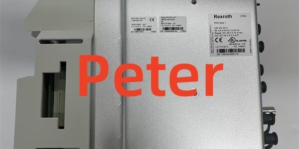
Product Core Brief
- Model: VM310, OEM part number 0608750109
- Brand: REXROTH (Bosch Rexroth industrial power module series)
- Series: VM modular cabinet power supply family
- Core Function: Convert single or three-phase 230 V AC mains to stabilized multi-channel DC auxiliary power for hydraulic valve amplifiers, motion PLCs, and servo drive logic circuits.
- Product Type: Vertical DIN rail mount AC-DC power converter with integrated cooling blower, front reset button and fault status LED indicators
- Key Specs: 2500 VA three-phase continuous power | 24 V 6 A main auxiliary output | 5.1 V 7 A logic supply | 1/3×230 V AC input | Condition: Refurbished Load-Tested Surplus
- Suffix variant notes: Base part 0608750109 supports 1-phase or 3-phase mains wiring; -102 / -103 suffix revisions carry identical electrical ratings with minor front panel label adjustments.
Product Introduction
The REXROTH delivers regulated multi-voltage DC power to VT hydraulic amplifiers, CML40 motion CPUs, and HCS/HMD servo drive control logic within shared automation cabinets. It eliminates separate low-current bench supplies for analog transducer and encoder circuits.This unit differs from lower-capacity VM200 variants by offering 2500 VA continuous three-phase power and a 10 kVA 5-second surge rating to absorb peak servo deceleration current spikes. OEM field data lists its rated MTBF at 40,000 operating hours under 24/7 cyclic cabinet loading at 40 °C ambient.
Key Technical Specifications
| Parameter | Value |
|---|---|
| Mains AC Input | 1×230 V or 3×230 V AC ±10 %, 50 / 60 Hz |
| Continuous apparent power (3-phase) | 2500 VA |
| Continuous apparent power (single-phase) | 1250 VA |
| Peak surge power (5 s max duty) | 10,000 VA |
| Primary DC intermediate bus range | 200 V DC min, 325 V DC nominal, 420 V DC max |
| Main Aux Output 1 | 24 V DC, 6 A continuous (±8 % voltage tolerance) |
| Logic Aux Output 2 | 5.1 V DC, 7 A continuous (±3 % voltage tolerance) |
| Negative Aux Output | -24 V DC, 0.5 A continuous (+20 / -10 % tolerance) |
| Cooling System | Internal axial blower forced convection, runtime fault monitoring |
| Mechanical Mount | Standard 35 mm vertical DIN rail rack housing |
| Unit Net Weight | 3.08 kg |
| Enclosure Protection Rating | IP20 cabinet-only installation |
| Full Rated Operating Temp | 0 °C to +55 °C with active blower airflow; linear power derate above 55 °C |
| Storage / Transport Temp Range | -20 °C to +70 °C, non-condensing 20–90 % RH |
| Altitude Derating Rule | 1 % power reduction per 1000 m above sea level; max 2000 m without isolation transformer |
| Built-In Protection Circuits | Mains overvoltage/undervoltage lockout, output short-circuit shutdown, over-temperature thermal trip, output overcurrent limiting |
| EMC & Compliance | EN 55011 Class A filtering, CE, UL, SEMI S2 cleanroom equipment qualified |
Quality Control Process (Engineer’s Perspective)
- Incoming Verification: Cross-reference serial number against Rexroth OEM 0608750109 part database; inspect blower fan blades for cracking, mains terminal lugs for corrosion, front reset button and LED indicators for physical damage. Photograph input/output terminal block pin layout for field wiring reference.
- Live Functional Test: Mount module to DIN rail test bench paired with combined VT-MACAS valve amplifier and CML40 PLC load banks; run 24 hour cyclic peak surge and steady-state continuous load profiles. Use a Fluke 115 signal logger to track 24 V / 5.1 V output voltage stability and blower runtime consistency.
- Electrical Parameter Test: 500 V Megger insulation test between mains input circuits and chassis ground (pass threshold >10 MΩ); validate output current limiting triggers at 110 % of rated auxiliary load without permanent shutdown.
- Protection & Indicator Verification: Simulate short-circuit on each DC output channel to confirm immediate power cut and fault LED activation; test front panel manual reset function to clear all fault latches without full mains power cycle.
- Final QC & Packaging: Replace aged electrolytic input/output capacitors and worn blower assemblies during refurbishment cycles; cap unused mains and DC output terminal ports with OEM plastic insulating plugs, seal unit in anti-static PE bag, apply dated QC Pass label listing output regulation accuracy, surge capacity, and thermal shutdown trigger test metrics before foam-lined carton packing.
Replacement Pitfall Guide
❗ Single / Three-Phase Input Wiring Mismatch Risk: The terminal block requires dedicated jumper positioning to switch between 1-phase and 3-phase mains supply. Incorrect jumper placement triggers constant undervoltage faults or permanent internal rectifier damage within 10 operating minutes. Photograph original jumper configuration before module removal.❗ Auxiliary Output Overload Miscalculation Risk: Sum total 24 V logic loads with a minimum 20 % current headroom before replacement. Stacking multiple VT analog amplifiers and CML40 CPUs can exceed the 6 A 24 V rated limit, causing voltage droop and unstable hydraulic position loop performance.❗ Blower Airflow Obstruction Hazard: Cable bundles covering front/rear ventilation slots block forced cooling airflow. Restricted airflow triggers unplanned thermal shutdown during peak 10 kVA surge events. Maintain a minimum 50 mm unobstructed clearance around all heat sink surfaces.❗ DC Output Cable Shielding Interference Risk: Unshielded low-voltage 24 V / 5.1 V auxiliary wiring run parallel to high-current mains cabling creates analog transducer signal noise and valve position oscillation. Separate low-voltage DC harnesses from AC mains looms by a minimum 50 mm inside cabinet trays.❗ ESD Control Circuit Damage: Front panel LED and reset logic PCB traces carry low electrostatic tolerance. Always rest the unit on a grounded anti-static mat during terminal block rewiring, especially in low-humidity cleanroom environments.Keep these in mind and you’ll cut 90% of rework time.
Compatibility Matrix & Benchmarks
Compatibility Matrix
- VM200 low-capacity power supply → : Needs Adaptation — recheck total cabinet auxiliary load current budget, retain identical mains wiring topology
- VT-MACAS-500-10/V0/I hydraulic amplifier → : Direct — 24 V auxiliary output natively supplies valve drive and transducer excitation power
- CML40.2-SP-330-NA-NNNN-NW motion PLC → : Direct — 24 V and 5.1 V dual auxiliary outputs match CPU control and logic supply requirements
- HCS02.1E-W0028-A-03-NNNN integrated servo drive → : Direct — drive 24 V control logic draws stable regulated power from module main auxiliary channel




