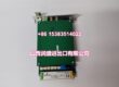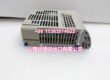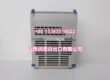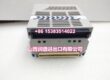
Product Core Brief
- Model: HCS02.1E-W0028-A-03-NNNN, OEM part R911298374
- Brand: REXROTH (Bosch Rexroth Indramat IndraDrive C series)
- Series: compact integrated servo converter family
- Core Function: Combine three-phase mains rectifier, DC bus buffer, and single-axis inverter to run MSK/IndraDyn S synchronous servos with full closed-loop motion control.
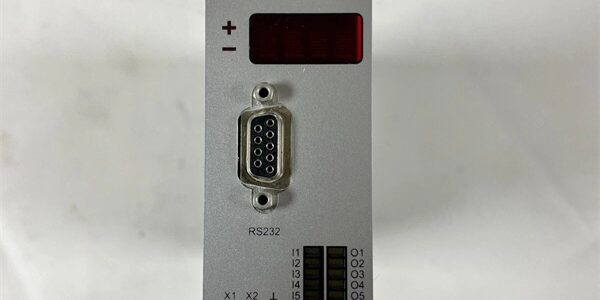
- Product Type: Vertical DIN rail all-in-one servo drive with internal cooling blower, no optional fieldbus/safety expansion cards populated
- Key Specs: 20.6 A continuous RMS output | 28.3 A peak overload | 5.1 kW continuous DC bus power | STO safe torque off | 3×200–500 VAC mains input | Condition: Refurbished Load-Tested Surplus
- Suffix breakdown: 02.1 = hardware revision 2.1; E = integrated mains feed-in converter; = 28 A peak output rating; A = base hardware variant; 03 = standard control logic firmware set; NNNN = empty expansion slots, no extra communication or safety add-on modules
Product Introduction
TXROTH .1E- eliminates separate mains rectifier units for standalone single-axis automation cells, pairing directly with MSK compact servo motors and coordinated by CML40 series motion PLCs over Ethernet or SERCOS buses. It embeds STO safe torque off logic without external safety relays.This unit differs from W0012 low-current variants by delivering 20.6 A continuous output to support mid-size vertical lifting and gantry axes. Field OEM data records its rated MTBF at 41,000 operating hours under 24/7 cyclic loading at 40 °C cabinet ambient, thanks to dedicated internal blower thermal management.
Key Technical Specifications
| Parameter | Value |
|---|---|
| Three-phase mains input voltage | 3×200–500 V AC ±10 %, 50 / 60 Hz |
| Continuous RMS motor output current | 20.6 A |
| Short-duration peak overload current | 28.3 A (60 s max duty within 10 min cycle) |
| Continuous DC bus power (no mains choke) | 5.1 kW |
| Maximum transient DC bus power | 8.0 kW |
| Nominal DC intermediate bus voltage | 560–700 V DC |
| PWM switching frequency selectable | 4 / 8 / 12 / 16 kHz |
| Max motor output frequency | 1600 Hz for high-speed spindle axes |
| Auxiliary control supply | 24 V DC (19.2–28.8 V), 0.8 A steady standby draw |
| Cooling system | Internal axial blower forced convection, runtime fault monitoring |
| Integrated safety function | STO Safe Torque Off category 3, PL d per EN ISO 13849 |
| Onboard signal interfaces | 8 digital 24 V DI / 4 digital DO; 1 differential ±10 V analog setpoint input; encoder feedback port for Hiperface / EnDat |
| Commissioning port | RS232 D-Sub for IndraWorks PC software parameter upload/download |
| Mechanical mounting | Standard 35 mm vertical DIN rail rack mount |
| Unit net weight | 5.0 kg |
| Enclosure protection rating | IP20 cabinet-only installation |
| Continuous operating ambient temp | 0 °C to +40 °C full rated power; linear performance derate above +40 °C up to 55 °C |
| Storage / transport temperature | -20 °C to +70 °C, non-condensing 5–95% RH |
| Built-in protection circuits | Mains phase loss, DC bus OVP/UVP, IGBT short-circuit, overcurrent, thermal shutdown, encoder cable break detection |
| Compliance certifications | CE, UL, EN61000 industrial EMC filtering, SEMI S2 cleanroom equipment qualified |
Quality Control Process (Engineer’s Perspective)
- Incoming Verification: Cross-reference serial number against Rexroth OEM R911298374 vital product databases; inspect blower fan blades for cracking, mains terminal lugs for corrosion, front D-Sub connector pins for bending. Photograph motor power, encoder, and I/O terminal pin layout for field installation reference.
- Live Functional Test: Mount unit to DIN rail test bench paired with MSK030C braked servo motor simulator; run 24 hour cyclic acceleration/deceleration load profiles. Use a Fluke 115 signal logger to track three-phase output current balance and blower runtime stability.
- Electrical Parameter Test: 500 V Megger insulation test between power stage IGBTs and chassis ground (pass threshold >10 MΩ); verify three-phase output current imbalance stays below 2% mismatch at full 20.6 A continuous load.
- Firmware & Safety Verification: Read and record factory IndraWorks runtime firmware revision via RS232 service port; trigger STO safety circuit to validate torque cut-off response time, retain axis parameter sets over a 12 hour power-off cycle to test non-volatile memory retention.
- Final QC & Packaging: Replace aged DC bus electrolytic capacitors and worn blower assemblies during refurbishment cycles; cap unused motor power and RS232 port openings with OEM plastic insulating plugs, seal unit in anti-static PE bag, apply dated QC Pass label listing PWM linearity, STO safety response, and thermal shutdown trigger test metrics before foam-lined carton packing.
Replacement Pitfall Guide
❗ W-Series Current Rating Mismatch Risk: W0012 low-current drives cannot replace this unit on mid-load vertical axes. Underrated current stages trigger persistent overcurrent faults during fast acceleration and stall holding cycles. Always cross-check motor continuous RMS current against drive rated output before swap.❗ Expansion Slot Empty Suffix Limitation: NNNN suffix hardware has no populated PROFIBUS or additional safety expansion cards. Machines requiring external fieldbus communication will need separate auxiliary communication modules wired to onboard Ethernet/RS232 ports.❗ Mains Cable Shielding Incompatibility: Unshielded three-phase mains wiring run parallel to low-level analog setpoint cables creates torque ripple and axis position drift. Separate mains power looms from analog signal harnesses by a minimum 50 mm inside cabinet cable trays.❗ Cabinet Airflow Obstruction Risk: Cable bundles covering front/rear blower ventilation slots block forced cooling airflow. Restricted airflow triggers unplanned thermal shutdown during sustained vertical axis holding at full 5.1 kW continuous power. Maintain 50 mm clearance around all drive heat sink surfaces.❗ ESD Encoder Circuit Damage: Onboard Hiperface/EnDat encoder transceiver ASICs carry low electrostatic tolerance. Always rest the unit on a grounded anti-static mat during encoder or I/O terminal rewiring, especially in low-humidity cleanroom environments.Keep these in mind and you’ll cut 90% of rework time.
Compatibility Matrix & Benchmarks
Compatibility Matrix
- .1E-W0012-ANNN → .1E- : Needs Adaptation — re-scale axis acceleration limits in motion program to match higher 28 A peak current capacity
- MSK030C-0900-NN-M1-NNN → .1E- : Direct — native Hiperface M1 encoder input and 20.6 A continuous output fully matches motor electrical ratings
- CML40.2-SP-330-NA-NW → .1E- : Direct — onboard Ethernet TCP/IP enables real-time motion setpoint exchange with SERCOS motion PLC
- VEP40.3CEN-256NN-MAD-1-FW → .1E- : Direct — analog fault status signals route through drive digital I/O terminals to HMI trending screens