
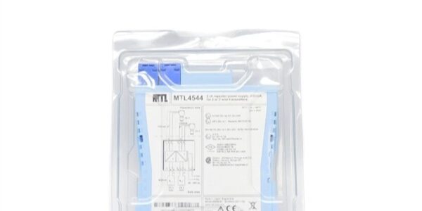
Product Core Brief
- Model: MTL5517
- Brand: MTL (Eaton Intrinsic Safety Division)
- Series: MTL5500 DIN-rail mounted intrinsically safe digital interface family
- Core Function: Galvanically isolate two independent NAMUR proximity/switch sensor inputs from Zone 0 hazardous gas manifolds, drive isolated relay contacts for safe-area discrete interlock logic with built-in line fault detection
- Product Type: Compact 15.8mm width DIN-rail plug-in IS barrier, separate blue hazardous-area and grey safe-area removable terminal plugs
- Key Specs: Dual NAMUR digital input channels | 1500VAC reinforced galvanic isolation | SIL2 simplex / SIL3 redundant IEC61508 | integrated LFD + phase reversal DIP switch configuration
- Note: Active OEM production; factory-new calibrated surplus and bench-tested refurbished inventory available. Mechanical and pinout incompatible with backplane-mount MTL4517 variant.
Key Technical Specifications
- Channel Configuration: Two fully independent galvanically isolated NAMUR sensor input channels
- Hazardous Field Supply: 7–9VDC sensor excitation via internal 1kΩ limiting resistor per channel
- Input Threshold Logic: Relay energizes when input current >2.1mA (closed switch / active prox); de-energizes <1.2mA (open circuit)
- Safe-Area Relay Contact Rating: 250VAC 2A resistive, 40VDC 2A resistive; Zone 2 load limited to 35V 2A 100VA
- Line Fault Detection (LFD): Detects short/open field wiring faults, triggers dedicated red LED and separate fault relay output; requires external 22kΩ/680Ω resistors on sensor loops
- Response Latency: Maximum 10ms channel switching response time for fast interlock trip logic
- Galvanic Isolation: 1500VAC reinforced separation between hazardous field circuit, safe relay circuit, and module power rail
- Power Input Range: 20–35VDC unregulated DC supply, maximum 35mA total draw at 24VDC nominal input
- Power Dissipation: 0.84W steady power draw under full dual-channel active load
- LED Status Indicators: Green = module power present; two yellow = channel active state; two red = line fault detection alarm
- Functional Safety Rating: SIL2 capable simplex (HFT=0); SIL3 capable with redundant dual-module 1oo2 architecture per IEC 61508
- Hazardous Location Certification: ATEX / IECEx Zone 0, IIC T4–T6; NEPSI, UL, SEMI S2 compliant
- Mechanical Mounting: Standard 35mm T-section DIN rail footprint, snap-lock mounting, overall width 15.8mm
- Operating Ambient Range: -20°C to +60°C continuous cabinet operation; derate LFD accuracy above +55°C
- EMC Compliance: EN61326 industrial process control noise immunity standard
Product Introduction
This DIN-rail digital intrinsic safety barrier isolates proximity and limit switch signals routed from explosive gas manifolds on Lam TCP9400 etch gas cabinets. It blocks high-amplitude 13.56MHz plasma RF noise from triggering false discrete interlock trips on VIOP digital I/O boards.Configurable DIP switches enable site-specific LFD and phase reversal logic without firmware edits, while isolated relay contacts eliminate ground loop offset drift between hazardous and safe control racks. Dual-channel layout cuts DIN rail space consumption by half versus single-channel MTL5511 barriers for dense fab safety I/O cabinets.
QA & Testing SOP (Transparency Building)
- Incoming Inspection: Cross-reference serial numbers against Eaton MTL trace databases; visual inspection for cracked terminal plug latches, burnt transformer windings, and damaged DIP switch sliders. All DIP switch factory default positions photographed pre-test.
- Live Bench Testing: Mount module to standard 35mm DIN rail; precision NAMUR signal simulator injects active/inactive fault-state currents across both channels for continuous 24-hour stability burn-in. Fluke process calibrator verifies relay contact continuity and LFD fault trigger thresholds.
- Electrical Testing: Megger insulation tester validates 1500VAC isolation resistance >10GΩ between hazardous and safe circuit sides; channel switching threshold error measured below 0.05mA full span.
- Calibration & Config Backup: Record factory LFD trigger current thresholds to internal test archive; document DIP switch configuration templates for post-install matching of existing cabinet logic.
- Final QC & Packaging: Secure loose terminal plug latches, wrap unit in anti-static foam, affix printed QC tag with isolation and switching threshold test metrics before sealed ESD bag packaging.
Installation Pitfalls & Guide (Engineer to Engineer)
❗ Backplane Variant Mismatch Risk: This unit only mounts to standard 35mm DIN rail; backplane MTL4517 cannot clip to DIN rail, and cannot slot into MTL4500 backplane racks. Terminal pin assignments differ entirely between the two variants, preventing direct cross-swap.❗ Hazardous/Safe Wiring Segregation Violation: Bundling blue hazardous-area sensor cables with grey safe-area relay wiring violates ATEX intrinsic safety rules; maintain minimum 50mm physical separation between signal looms inside cabinet trunking.❗ LFD Resistor Omission Hazard: LFD circuit will fail to detect open/short wiring faults if mandatory 22kΩ/680Ω loop resistors are not fitted to each NAMUR sensor line, creating unmonitored gas cabinet safety blind spots.❗ Relay Minimum Load Violation: Safe-area relay loads must draw ≥50mW minimum current; low-impedance logic inputs below this threshold cause intermittent contact chatter and inconsistent interlock state reporting to VIOP I/O boards.❗ Catastrophic ESD Damage Risk: Internal isolation transformer windings and LFD signal conditioning ICs sustain permanent damage from ungrounded handling; certified ESD wrist strap and grounded anti-static mat mandatory before touching terminal plugs or PCB housing.4-Step Replacement Guide:
- Pre-install: Lock out hazardous-area gas supply isolation valves, export all discrete interlock threshold tables via tool HMI; cut DIN rail 24VDC power supply per lockout-tagout protocols.
- Removal: Unlatch blue hazardous and grey safe-area terminal plugs one at a time, depress DIN rail bottom release tab to slide module free, place unit on ESD foam. Record original DIP switch slider positions for matching configuration.
- Install: Snap replacement module onto 35mm DIN rail, restore DIP switch positions to photographed settings, fit mandatory LFD loop resistors to sensor wiring, re-terminate hazardous and safe signals to matching terminal pinouts.
- Power-on Test: Restore 24VDC DIN rail supply, confirm green power LED illuminates, run 30-minute continuous active/fault state cycling to validate relay switching and reliable LFD fault alarm triggering.
FAQ (Frequently Asked Questions)
Q: Can replace backplane-mounted MTL4517 on existing TCP9400 gas cabinet control racks?A: No direct drop-in swap possible. uses DIN-rail snap mounting while MTL4517 locks to dedicated MTL4500 backplanes; terminal pin mapping and power contact layout differ completely. Full cabinet wiring rework is required to install in backplane rack layouts.Q: Does this barrier support hot-swapping while gas manifolds remain pressurized and DIN rail power live?A: Live removal disconnects galvanic isolation circuits mid-operation, exposing safe-area VIOP digital I/O hardware to RF transients that corrupt interlock logic state registers. Full 24VDC rail power lockout and hazardous gas valve isolation shutdown are mandatory before extraction.Q: What warranty separates factory-new surplus stock from calibrated refurbished units?A: Factory-new Eaton-certified stock carries a 12-month industrial warranty covering isolation breakdown and switching threshold drift. Refurbished calibrated units ship with a 6-month limited warranty; aged transformer insulation develops gradual leakage resistance under continuous cabinet heat and plasma RF exposure.Q: Will swapping this digital barrier erase stored gas cabinet interlock trip thresholds?A: All discrete safety logic calibration data resides on the host VIOP analog/digital I/O board’s onboard flash memory, independent of the barrier module’s internal circuitry. Export full interlock configuration profiles via the tool HMI pre-replacement to match existing sensor trip points post-install.Q: Can this hardware operate with Lam etch tools running legacy PCS v6.x software without driver modification?A: No software patch required. The unit outputs passive dry relay contact signals compatible with all discrete digital input register mapping used across PCS v6.0 through v9.0 releases; LFD fault alarm signals register as standard digital fault inputs without custom firmware edits.Q: What expected service window applies in 24/7 high-volume fab cabinet operation?A: Factory-new units target scheduled replacement at 47,000 operating hours. Refurbished variants degrade at 38,000 hours; transformer insulation leakage increases over time, raising false interlock trip frequency and triggering unplanned wafer batch aborts during production runs.Q: Can a single connect two separate Zone 0 NAMUR proximity sensors simultaneously?A: Yes, each channel operates with full galvanic isolation between sensor loops; cross-talk between the two digital signals measures below 0.01mA full span. Independent LFD fault monitoring runs on each sensor circuit without signal interference across channels.




