
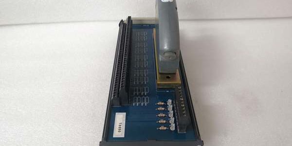
Product Core Brief
- Model: T8850
- Brand: ICS Triplex (Rockwell Automation)
- Series: Trusted TMR Safety Control Series ⚠️ EOL — limited new surplus stock remaining
- Core Function: Marshal and buffer 40 analog or digital output signals between TMR output I/O modules and field actuators
- Product Type: Mixed Signal Output Field Termination Assembly (FTA)
- Key Specs: 40 split into five 8-channel isolated groups | SmartSlot hot-swap edge connector | No onboard channel fusing (external protection required) | Condition: New Original Surplus
Product Introduction
The ICS Triplex T8850 acts as the cabinet wiring hub for Trusted TMR output modules, routing 24 VDC command signals to valves, solenoids, and analog positioners without direct field wiring to backplane cards. It reduces I/O module wear by isolating hot-swap maintenance from live field cabling.This FTA differs from input-focused T8800 via mixed analog/digital signal compatibility and five galvanically separated channel banks. Its published shock rating withstands 15 g mechanical transients, per OEM environmental qualification test data.
Key Technical Specifications
| Parameter | Value |
|---|---|
| Total Output Channels | 40, split into five isolated banks of 8 channels each |
| Nominal Operating Voltage | 21 VDC to 28 VDC (24 VDC standard field supply) |
| Channel Isolation Rating | 250 V basic isolation, tested 2436 VDC for 60 second withstand |
| Backplane Interface | SmartSlot gold edge connector for T8451 / T84611 / T8480 output modules |
| Field Terminal Wire Range | 12 AWG to 28 AWG screw-clamp terminals |
| Onboard Indicators | Single LED per bank for field power presence |
| Max Continuous Power Draw | 6 W fully loaded across all 40 channels |
| Mechanical Mounting | Standard 35 mm horizontal DIN rail |
| Operating Ambient Temp | 0 °C to +60 °C; storage -25 °C to +70 °C |
| Safety Certification | IEC 61508 SIL 3, TÜV, UL/cUL, CE, IP20 cabinet-only |
| Physical Dimensions | 30.2 cm × 12.5 cm × 6.2 cm; net weight 0.62 kg |
| Overcurrent Protection | No per-channel fuses; external circuit breakers required for field loops |
Quality Control Process (Engineer’s Perspective)
- Incoming Verification: Cross serial numbers against Rockwell OEM batch manifests to filter counterfeit aftermarket units. Visually scan PCB traces for cold solder joints, bent SmartSlot pins, and cracked terminal block plastic.
- Live Functional Test: Mount on DIN rail test bench, connect a Fluke 115 regulated 24 VDC supply, mate a production T8451 digital output card. Run a 24-hour soak cycle with simulated valve load resistors, log channel group power LED state hourly.
- Electrical Parameter Test: Use a 500 V Megger to measure insulation resistance between isolated channel banks and chassis ground; pass threshold is >10 MΩ. Verify continuity across each group’s shared field power rail.
- Component Verification: This passive termination base contains no firmware. Inspect all screw terminal clamps for consistent torque retention; photograph terminal layout for site wiring reference records.
- Final QC & Packaging: Place full assembly inside static-dissipative poly bag. Affix dated QC Pass sticker listing measured insulation resistance and total soak test runtime before palletized storage.
Replacement Pitfall Guide
❗ Module Pairing Mismatch Risk: The only mates with T8451, T84611, T8480 output I/O cards. Pairing it with T8403 digital input modules creates open signal paths the SIS safety logic flags as critical faults.❗ Terminal Group Isolation Misconfiguration Risk: Each 8-channel bank uses an independent field power feed. Jumping power rails between separate banks erases galvanic isolation and introduces cross-loop noise that distorts analog 4–20 mA output signals.❗ Cable Shield Grounding Incompatibility Risk: The chassis ground lug bonds to cabinet protective earth. Grounding field cable shields at both the FTA and actuator creates ground loops that inject low-frequency noise into analog control loops.❗ Power Supply Headroom Miscalculation Risk: A fully populated draws 6 W at 24 VDC. Size cabinet power supplies with 20% overhead; underrated supplies drop voltage below 21 VDC and trigger SIL3 safe-state interlocks.❗ ESD Damage Risk: SmartSlot gold contacts remain exposed when the I/O module is removed. Use a grounded anti-static mat during card swaps in low-humidity cabinet spaces; static discharge scratches plating and generates intermittent channel dropout faults.Keep these in mind and you’ll cut 90% of rework time.
Compatibility Matrix & Benchmarks
Compatibility Matrix
- T8451 (40-Ch Digital Output Module) → : Direct Replacement — Native SmartSlot mechanical and electrical matching, zero wiring rework
- T8800 (40-Ch Digital Input FTA) → : Needs Adaptation — DIN rail footprint identical, channel isolation and signal direction differ; full terminal rewiring required
- T8403 (Digital Input Module) → : Incompatible — Input signal conditioning circuits cannot drive actuator output loads
Benchmarks
- Full bank signal propagation delay: 180 µs (simulated 4–20 mA analog actuator load, 24 VDC nominal supply)
- Inter-group isolation resistance: >10 MΩ between separate 8-channel banks (500 V Megger test)
- Continuous power consumption: 5.2 W average under full 40-channel mixed analog/digital load





