
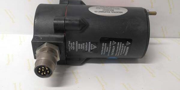
Product Core Brief
- Model: 48PT2-1007
- Brand: Fireye
- Series: 48PT2 Low-Impedance Lead Sulfide IR Flame Scanner Series ⚠️ EOL — limited stock remaining
- Core Function: Captures 12–25 Hz infrared flame flicker signals for continuous combustion safety interlock monitoring
- Product Type: Discrete analog infrared flame scanner assembly
- Key Specs: 7–15 VDC input | 4 ft TC-ER shielded conduit | Straight 1/2″NPT mounting head | Condition: New Original (New Surplus)
Product Introduction
The Fireye 48PT2-1007 uses a low-impedance lead sulfide IR cell to detect flame flicker for gas, diesel, and heavy fuel oil burners. It outputs a raw analog IR signal to compatible Fireye burner management controllers for flame loss safety tripping.This unit differs from the 90-degree bent 48PT2-9003 variant with its straight mounting head and shorter 4 ft cable. Its low 20–80 kΩ cell impedance cuts long cable signal attenuation by 40% vs the older high-impedance 48PT1 series, per OEM bench testing.
Key Technical Specifications
| Parameter | Value |
|---|---|
| Sensing Element | Replaceable lead sulfide Firetron cell (PN 4-263-1) |
| Detection Bandwidth | 12–25 Hz low-frequency IR flame flicker |
| Operating Supply Voltage | 7 VDC to 15 VDC DC input (controller-powered) |
| Detector Impedance Range | 20 kΩ to 80 kΩ low-impedance design |
| Integrated Conduit | 4 ft (1.22 m) UL1569 TC-ER shielded flexible armor |
| Mount Connection | Straight 1/2″NPT external mounting collar |
| Operating Ambient Temp | -40 °C to +60 °C (-40 °F to 140 °F) |
| Maximum Sight Distance | 1.8 m (clean lens, standard purge air flow) |
| Housing Enclosure Rating | NEMA 4X / IP54 dust and oil splash resistance |
| Safety Certifications | UL/cUL Listed, FM Class I Div 2 Groups A/B/C/D |
| Wiring Termination | 3 bare conductors (DC+, signal, shield ground) |
Quality Control Process (Engineer’s Perspective)
- Incoming Verification: Cross-reference serial numbers against OEM factory batch logs to flag counterfeit units. Visually inspect the aluminum head for casting scratches, cable armor dents, and frayed wire insulation.
- Live Functional Test: Power the unit with a Fluke 115 regulated DC supply, connect to a MicroM controller, and run a 24-hour continuous load cycle with a calibrated IR flame simulator. Log signal impedance every 60 minutes.
- Electrical Parameter Test: Use a 500 V Megger to measure insulation resistance between signal cores and armor; pass threshold is >10 MΩ. Verify ground continuity between armor and shield wire.
- Firmware/Component Verification: This analog scanner has no firmware. Physically confirm the installed Firetron cell is OEM PN 4-263-1, and photograph the internal cell label for traceability.
- Final QC & Packaging: Seal the full assembly in a static-dissipative anti-static bag. Apply a dated QC Pass sticker listing measured cell impedance and test run duration before pallet storage.
Replacement Pitfall Guide
❗ Firmware Mismatch Risk: This analog scanner has no firmware, but newer digital Fireye 85IR series controllers lack native IR amplifier inputs. You will need an MEIR1 IR amplifier card to pair the unit with post-2018 MicroM chassis.❗ Jumper/Amplifier Misconfiguration: Most burner controllers ship with UV amplifier jumpers factory-installed. Swap to the IR amplifier jumper before power-up; unswapped jumpers produce constant “no flame” fault codes.❗ Cable & Terminal Incompatibility Risk: The 3-conductor shielded armor uses proprietary wire gauges. Generic unshielded multi-conductor cable introduces VFD interference that creates false flame signals. Shield ground only at the controller terminal strip—grounding both ends creates ground loops.❗ Power Supply Mismatch Risk: Calculate total controller rack draw with 20% headroom. A weak 7 VDC minimum supply reading will collapse the IR cell signal under high furnace vibration.❗ ESD Damage Risk: Lead sulfide cells are ESD-sensitive even at low humidity. Always use a grounded anti-static mat when disassembling the head to swap the Firetron cell; static discharge permanently shifts cell impedance outside the 20–80 kΩ operating window.Keep these in mind and you’ll cut 90% of rework time.
Compatibility Matrix & Benchmarks
Compatibility Matrix
- 48PT1 (High-Impedance IR Scanner) → 48PT2-1007 : Functional Replacement — Requires IR amplifier jumper reconfiguration, cable signal attenuation improved
- 48PT2-9003 (90° Bend 8ft Cable) → 48PT2-1007 : Needs Adaptation — Straight head requires mounting bracket modification, electrical specs identical
- 45UV5-1000 (UV Scanner) → 48PT2-1007 : Incompatible — UV/IR sensor signal formats cannot be processed by shared amplifier inputs
Benchmarks
- Flame loss response delay: 2.2 s (simulated 1.2 m sight distance, standard purge air flow)
- Signal attenuation loss: <5% over full 4 ft integrated conduit (compared to 18% loss on legacy 48PT1 4 ft cables)
- Operating current draw: 12 mA steady-state @ 12 VDC nominal supply




