
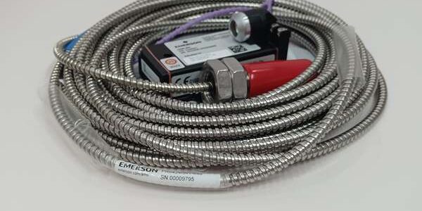
Product Core Brief
- Model: PR6424/000-030 (Probe Assembly) + CON021 (Single Channel Rack Preamplifier)
- Brand: EPRO (Emerson Machinery Health Monitoring, Germany)
- Series: M18 eddy current probe series, matched exclusively with CON021 for MMS3000 / A6000 turbo machinery protection racks
- Model Code Decode: = M18×1.5 thread, 18mm probe head, ±2mm full linear measuring range (for axial thrust + radial vibration)/000 = 0-meter integrated factory cable (no built-in braided cable at probe body)-030 = Bare open braided cable terminals, no molded Lemo plug, field custom wiring required
- Core Function: Factory pre-calibrated non-contact eddy current measurement kit for simultaneous radial shaft vibration and long-range axial thrust displacement on steam/gas turbines, centrifugal compressors and critical rotating equipment SIL safety protection loops, fully compliant with API 670 machinery protection standards
- Product Type: Complete matched eddy current sensing kit (M18 probe head + bare cable termination + rack-mount signal conditioner)
- Key Specs: M18×1.5 stainless steel housing, 18mm sensing tip; ±2mm total linear measuring range; factory calibrated 4V/mm sensitivity paired with ; bare open cable end without Lemo molded plug, field terminal wiring designNote: Discontinued legacy machinery monitoring hardware, stocked as unopened factory calibrated new surplus; probe and must be used as a matched set to guarantee linear measurement accuracy.
Key Technical Specifications
/000-030 Probe Assembly
- Mechanical Structure
- Thread standard: M18 × 1.5 stainless steel heavy-duty housing for turbine bearing housing mounting
- Sensing head diameter: 18mm large target coverage, stable signal for large-diameter rotors
- Cable code definition: /000 = zero built-in probe cable; -030 = bare stripped braided coaxial cable ends, no factory Lemo plug
- Minimum cable bend radius: ≥50mm for all field-extended coaxial cable, sharp bends prohibited
- IP rating: Probe sensing head IP67, bare cable field routing IP65 cabinet grade
- Measurement Performance
- Full linear measuring span: ±2 mm (4mm total travel, ideal for axial thrust bearing monitoring)
- Recommended installation nominal midpoint air gap: 2.7 mm
- Calibrated sensitivity (matched ): 4 V/mm (101.6 mV/mil)
- Maximum linearity error: ≤ ±1.5% full measurement span
- Frequency response: DC ~ 10 kHz (-3dB), covers full turbine vibration and slow thrust displacement spectrum
- Thermal drift index: Zero point drift 200mV / 100K; sensitivity drift ≤0.3% full scale per 100K
- Long-term zero drift: ≤0.3% FS over 12 months continuous turbine operation
- Thermal & Environmental Limits
- Probe head continuous working temperature: -35°C ~ +180°C; transient peak short-term +200°C
- Field extended braided cable temperature rating: Max 200°C high-temperature PTFE insulation
- Storage & transport temperature: -40°C ~ +70°C
- Vibration resistance: 5g continuous vibration at 60Hz bearing housing mounting
- Working ambient pressure: Uniform 2bar external process cabinet environment
- Minimum target rotor diameter: 40mm carbon steel shaft; stainless steel/aluminum coated rotors require on-site recalibration
Matched Single Channel Preamplifier Reference Parameters
- Input power supply: DC 10–30 V rack supply (standard 24VDC MMS3000 monitoring chassis)
- Probe excitation output: -26.75 VDC short-circuit protected sensor excitation power
- Analog output signal: Linear buffered voltage 0~8VDC proportional to shaft gap; requires receiving DCS/monitor card load impedance ≥10kΩ
- Galvanic isolation: Complete isolation between field probe measuring circuit and rack backplane bus to eliminate ground loop noise
- Cabinet operating temperature: -20°C ~ +60°C
- Form factor: Single-slot 3U DIN41612 standard 19” rack plug-in module
- PCB protection: Full acrylic conformal coating for offshore and refinery corrosive cabinet atmospheres
Combined Kit Mechanical Data
- /000-030 probe net weight: ~0.14kg
- module dimensions: 128mm H × 25mm W × 160mm D; weight ~0.38kg
Product Introduction
This M18 large-range eddy current matched kit is the standard dedicated sensor for turbine axial thrust displacement measurement, simultaneously supporting radial rotor vibration monitoring, widely used in power plant steam turbines, gas turbines and petrochemical large centrifugal compressors critical protection systems. Adopting non-contact eddy current induction measurement principle, there is no mechanical friction contact between probe tip and rotating metal shaft, avoiding long-term wear and measurement drift under high-temperature bearing housing operating conditions.The suffix /000-030 design means the probe has no factory integrated cable and bare open wire terminals, supporting users to customize extended coaxial cable length on-site according to the distance between bearing housing and marshalling cabinet, flexible to adapt complex wiring layout of long-distance machinery houses.Factory calibrated matched with preamplifier, the kit converts tiny coil inductance changes into standard linear 4V/mm analog voltage signals, compatible with MMS3000 monitoring racks, PLC and DCS safety trip interlock logic. Matched pair calibration eliminates on-site micrometer zero/gain adjustment during equipment maintenance shutdowns, greatly shortening turbine downtime for sensor replacement.
QA & Testing SOP (Transparency Building)
- Incoming Inspection: Cross-reference unique serial calibration numbers printed on probe and factory calibration certificate; inspect 18mm probe tip for scratches, braided coaxial cable insulation damage, bare terminal wire breakage and rack module pin bending; verify original anti-static packaging and calibration certificate seal integrity.
- Live Bench Calibration Test: Mount probe on precision micrometer gap test jig, powered by Fluke stabilized 24VDC regulated supply paired with matched ; run 24-hour continuous full ±2mm gap sweep testing, record linearity error, zero thermal drift and 4V/mm sensitivity output under 25°C room temp and 60°C simulated cabinet operating temperature.
- Electrical Insulation Test: Megger insulation resistance >10MΩ between cable shield and rack ground; perform vibration cycle test to confirm bare cable terminal connection maintains stable signal without intermittent measurement dropout.
- Calibration Record Backup: Archive original factory calibration certificate recording nominal midpoint air gap, calibrated sensitivity and linearity tolerance; document rear terminal block wiring polarity for field maintenance reference.
- Final QC Packaging: Attach serialized printed test pass tag with full linearity test data; separate probe and preamplifier with foam padding to avoid scratching sensing tip, seal complete kit in foam-lined static-shielded bag for warehouse storage and transit protection.
Installation Pitfalls & 4-Step Replacement Guide
❗ Calibration Matching Risk: Probe and preamplifier must be deployed as a complete factory-matched kit. Cross-matching with unmatched units will cause severe linearity deviation, resulting in invalid turbine thrust/vibration safety trip threshold judgment.❗ Air Gap Misadjustment Risk: Standard nominal midpoint installation gap = 2.7mm; operation outside the 1.5mm ~ 3.5mm linear window will clip analog output signals and create blind thrust displacement fault conditions on critical SIL safety protection systems.❗ EMI Interference Risk: Route all field-extended probe coaxial cable completely separated from high-current VFD and motor power cables; parallel power wiring induces electromagnetic noise and triggers false thrust/vibration alarm signals on DCS monitoring screens.❗ Target Material Deviation Risk: Factory calibration parameters only apply to standard carbon steel rotors; stainless steel, aluminum or coated shaft surfaces change measurement sensitivity and require full on-site recalibration.❗ ESD Circuit Damage Risk: Ungrounded technicians touching bare probe cable terminals or rack connector pins will damage the internal oscillator circuit inside the preamplifier; latent ESD damage causes slow zero drift that emerges after 2–4 weeks of continuous turbine runtime.
4-step replacement guide:
- Pre-install LOTO: Lock out rotating turbine machinery and MMS3000 rack 24VDC power supply; attach grounded anti-static wrist strap to cabinet DIN rail ground bus; photograph original probe mounting thread depth and rear terminal wiring polarity for reference.
- Removal: Unscrew legacy M18 probe from bearing housing mount; carefully coil extended coaxial cable while maintaining ≥50mm minimum bend radius; disconnect bare cable terminals from old terminal block, extract preamplifier from rack slot and label all power/signal wiring.
- Hardware Install: Thread new /000-030 probe into bearing mount; adjust lock nut to set 2.7mm nominal air gap measured via precision feeler gauge; route field coaxial cable away from high-current power wiring; terminate bare -030 cable ends to new rear terminal block following original polarity; insert into empty MMS rack slot and fasten front locking screws.
- Power-on Validation: Restore rack power supply; use micrometer gap test jig to verify linear 4V/mm analog output across full ±2mm travel range; access MMS/DCS monitoring screens to confirm stable zero offset, no noise spikes and valid axial thrust + radial vibration readings without false safety interlock alarms.
FAQ
Q: Can /000-030 simultaneously measure radial vibration and axial thrust displacement?A: Yes. The ±2mm full linear range supports both measurement functions. For high-reliability turbine protection, it is standard to install two independent probes: one for axial thrust monitoring and one PR6423 for radial vibration measurement on each bearing housing.Q: Does the preamplifier support hot-swapping while the MMS3000 rack remains energized?A: The rack module supports live slot extraction, but all bare probe cable terminals must be fully disconnected from the terminal block first. Live disconnection of probe wiring generates inductive voltage transients that damage the preamplifier internal oscillator circuit.Q: What warranty coverage applies to bench-tested calibrated /000-030 + full kits?A: All stocked calibrated kits carry a 12-month functional warranty covering factory calibration linearity, probe coil integrity, cable terminal and preamplifier signal processing circuit defects. Damage caused by improper air gap adjustment, unshielded EMI wiring, reversed rack power polarity or ungrounded ESD handling is excluded from warranty coverage.Q: Is there a direct drop-in modern replacement for this discontinued series kit?A: Emerson’s current EZ1180 M18 eddy current probe provides equivalent long-range measurement performance, but rack pinout, bare cable terminal wiring and 4V/mm sensitivity scaling are inconsistent. Full cabinet wiring re-termination and DCS thrust trip threshold revalidation are mandatory with no unmodified direct swap solution.Q: What is the difference between suffix -030 and -010 on probes?A: -030 = bare stripped open cable wire ends, manual terminal wiring to /CON031 preamplifiers; -010 = factory molded Lemo self-locking plug, direct plug-and-play front port connection for without field wiring.Q: Can multiple probes share a single preamplifier?A: Not supported. is a dedicated single-channel signal conditioner designed for one calibrated probe only. Additional thrust/vibration measurement points require independent full matched probe + kits for each monitoring channel.Q: What does /000 stand for in /000-030 model code?A: /000 indicates the probe body has zero meters of factory pre-integrated braided cable; users need to purchase and connect custom-length high-temperature coaxial cable on-site between probe head and preamplifier.




