Product Core Brief
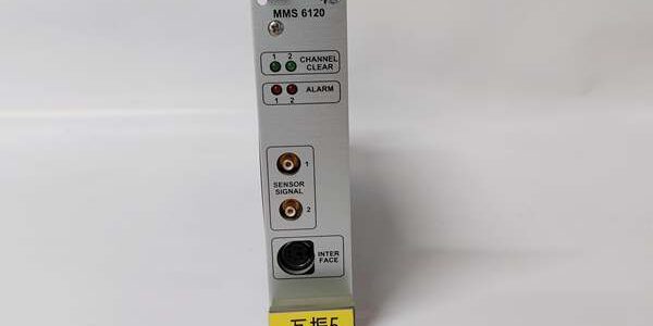
- Model: MMS6120
- Brand: EPRO (Emerson Machinery Health, Germany)
- Series: MMS6000 modular rack machinery protection system
- Core Function: Dual independent channel monitor for eddy current probe signals, measures radial shaft vibration, rotor displacement, bearing clearance and eccentricity for steam/gas turbines, centrifugal compressors and large critical rotating equipment safety protection, fully compliant with API 670 standard
- Product Type: Single-slot hot-swappable rack-mounted vibration/displacement monitoring module
- Key Specs: 2 galvanically isolated eddy current input channels; compatible CON021 preamplifier 0–16V linear gap signals; independent overspeed/vibration alarm SPDT relays; isolated 4–20mA analog output per channel; front panel local parameter configuration portNote: Discontinued end-of-life machinery protection hardware, stocked as unopened factory-calibrated new surplus; exclusively matched with EPRO PR6423 / PR6424 eddy current probe + CON021 preamplifier assemblies.
Key Technical Specifications
Input Channel & Sensor Compatibility
- Dual fully galvanically isolated analog input channels (CH1 / CH2)
- Supported input signal: 0–16VDC linear gap voltage from CON021 preamplifier (4V/mm / 8V/mm sensitivity)
- Input impedance: >100 kΩ, short-circuit protected
- Measuring range configurable: ±1mm / ±2mm full span matching PR6423 / PR6424 probe linear window
- Signal frequency bandwidth: DC ~ 10kHz, covers low-frequency thrust displacement and high-frequency rotor vibration signatures
- Per-channel diagnostics: Sensor break detection, signal overrange/underrange fault, preamplifier power loss alarm
Power & Output Circuits
- Rack supply: Nominal +24 VDC, dual redundant power input for fault tolerance
- Analog outputs: Independent isolated 4–20mA proportional output per channel (0mA = minimum gap, 20mA = maximum gap), minimum load resistance 500 Ω
- Alarm relays: Isolated SPDT dry contact per channel (high vibration, low/high gap, sensor fault); contact rating 250VAC / 30VDC 5A resistive load
- Front buffered test signal output: Repeats raw gap voltage for on-site oscilloscope troubleshooting without rack shutdown
Communication & Configuration
- Front Mini-DIN RS232 local configuration port: Set measuring range, alarm thresholds, filter parameters via MMS6000 PC service software
- Rear RS485 field bus: Connects to MMS68xx centralized host for long-term vibration/displacement historical trending data upload
- Hot-swap design: Module removable live without full rack power shutdown
Environmental & Mechanical
- Rack form factor: Single slot 3U DIN 41612 48-pin rear connector, standard 19-inch MMS6000 chassis
- Operating cabinet temperature: -20°C ~ +60°C; storage temperature -40°C ~ +70°C
- Humidity tolerance: 5%–95% non-condensing; full acrylic conformal coated PCB for refinery/offshore corrosive cabinet atmospheres
- Hazardous certification: FM Class I Div 2 Groups A/B/C/D cabinet mounting certified, ISO 10816 machinery vibration compliance
- Unit weight: 0.95 kg; dimensions 128mm H × 25mm W × 160mm D
Product Introduction
This dual-channel rack monitor is the core measurement module of the MMS6000 machinery protection system, dedicated to processing linear gap signals transmitted by CON021 preamplifiers paired with PR6423/PR6424 eddy current probes. Two independent isolated measurement paths support simultaneous monitoring of two separate bearing vibration points or redundant displacement measurement on a single rotor, meeting SIL-compliant critical machinery safety protection requirements.It converts 0–16V analog gap signals into real-time vibration peak-to-peak values and shaft clearance displacement values, with independently configurable high/low alarm thresholds. When vibration or gap exceeds set limits, the module triggers isolated SPDT relay contacts to output trip interlock signals to plant DCS safety logic. Independent 4–20mA analog outputs transmit continuous measurement data to PLC and monitoring systems for real-time display and trending analysis.Built-in sensor break and signal overrange fault detection identifies broken probe cables, failed CON021 preamplifiers or abnormal shaft clearance changes in advance, eliminating blind measurement faults on turbine safety loops. Front test output simplifies field troubleshooting without interrupting rack operation, while redundant rack power supply design avoids single-point power failure risks.Typical deployment: Power plant steam/gas turbine bearing radial vibration, compressor thrust bearing axial displacement monitoring, critical blower rotor clearance protection.
QA & Testing SOP (Transparency Building)
- Incoming Inspection: Cross-reference OEM serial batch production logs; inspect front Mini-DIN configuration port, rear 48-pin rack connector, front status LED panel for scratches, bent pins or cracked housing; verify original factory anti-static packaging seal integrity.
- Live Bench Testing: Install module in MMS6000 test rack powered by Fluke stabilized dual redundant 24VDC supply; connect programmable 0–16V signal simulator to both input channels, run 24-hour continuous full-range gap sweep testing, validate vibration/gap alarm relay trip logic and 4–20mA analog output linearity.
- Electrical Isolation Test: Megger insulation resistance >10MΩ between analog input circuits, rack power supply and alarm relay output circuits; confirm short-circuit input protection activates without module hardware damage.
- Configuration Backup: Capture factory default parameter template (measuring span, vibration alarm setpoints, signal filter bandwidth) via service software, document RS485 bus wiring polarity for field maintenance reference.
- Final QC Packaging: Attach serialized printed test pass tag listing measurement linearity and relay trip test results; seal unit in foam-lined static-shielded bag to protect rear rack connector pins during warehouse storage and transit.
Installation Pitfalls & 4-Step Replacement Guide
❗ Firmware Compatibility Risk: rack chassis firmware V1.15 and older lack dual-channel redundant fault history logging; upgrade rack firmware to V1.30+ before module swap to avoid blind vibration measurement failure conditions on turbine safety loops.❗ Measuring Span Parameter Mismatch Risk: Incorrectly configured ±1mm / ±2mm measuring range creates severe vibration reading deviation and false safety trips; record original span configuration via software before removing legacy .❗ Sensor Wiring EMI Interference Risk: Route preamplifier shielded signal cables fully separated from VFD and high-current motor power cables; parallel power wiring induces noise interference triggering false vibration gap alarms.❗ Redundant Power Miswiring Risk: Single-sided rack 24V supply connection eliminates redundant power fault tolerance, violating API 670 machinery protection design specifications.❗ ESD Circuit Damage Risk: Ungrounded technicians touching rear rack connector pins destroy front-end signal comparator circuits; latent ESD damage creates intermittent vibration signal dropout surfacing after 2–4 weeks of continuous turbine runtime.
4-step replacement guide:
- Pre-install LOTO: Lock out turbine rotating machinery and rack dual 24VDC power supply; attach grounded anti-static wrist strap to rack DIN rail ground bus; photograph rear 48-pin wiring terminal mapping and front Mini-DIN configuration cable layout for reference.
- Removal: Unscrew front panel locking fasteners, slide legacy straight out of live hot-swap slot; disconnect analog input wiring, RS485 communication bus wiring, 4–20mA analog output and alarm relay wiring channel by channel.
- Hardware Install: Slide new fully into vacant 3U rack slot, hand-tighten front mounting screws; replicate all rear wiring polarity from photo reference, reconnect dual redundant rack 24V power feeds and preamplifier signal cables.
- Power-on Validation: Restore rack power supply; connect laptop via front Mini-DIN port, load original measuring span and vibration alarm threshold configuration; simulate full gap signal sweep to verify linear 4–20mA output, alarm relay trip activation and stable vibration/gap measurement without noise-induced false fault alerts.
FAQ
Q: Can support redundant 1oo2 vibration protection for SIL3 turbine safety systems?A: A single provides dual independent sensor input channels for redundant measurement on one bearing; full SIL3 vibration protection compliance requires two separate modules in distinct rack slots with physically separated probe cable routes for 1oo2 safety voting logic.Q: Does support hot-swapping while the rack remains fully energized?A: The hardware is rated hot-swappable, but all field input, analog output and alarm relay wiring must be disconnected before extracting the module to avoid inductive voltage transients damaging internal signal processing circuits.Q: What warranty coverage applies to bench-tested surplus units?A: All stocked modules carry a 12-month functional warranty covering rack communication, analog input comparator, 4–20mA output and alarm relay circuit defects. Damage from misconfigured measuring span parameters, unshielded sensor wiring EMI, reversed rack power polarity or ungrounded ESD handling is excluded from coverage terms.Q: Is there a direct drop-in modern replacement for discontinued ?A: Emerson’s current CSI 6500 vibration monitor series offers equivalent dual-channel gap/vibration measurement functionality, but rear 48-pin pinout, front Mini-DIN configuration port and software parameter mapping differ; full cabinet wiring retermination and turbine vibration trip logic revalidation is mandatory with no unmodified direct swap capability.Q: Can simultaneously measure radial vibration and axial thrust displacement on two different bearing points?A: Yes. Each channel supports independent measuring span configuration (±1mm for radial vibration, ±2mm for axial thrust), enabling simultaneous monitoring of two distinct bearing measurement points on one single-slot module.Q: Can receive raw eddy current probe signals directly without preamplifiers?A: Not supported. The module only accepts conditioned linear 0–16V gap voltage output from preamplifiers; raw unconditioned probe coil signals lack stable linearity and cannot be processed by input circuits.Q: Can the 4–20mA analog gap output connect directly to standard DCS analog input cards?A: Yes, the isolated 4–20mA drive circuit supports standard DCS AI card loads ≥500 Ω; for low-impedance PLC analog inputs (<200 Ω), install external signal isolation barriers to prevent output loading and vibration reading drift.