
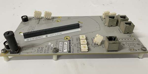
Product Core Brief
- Model: CC-TCNT01 (OEM PN: 51308307-175)
- Brand: Honeywell
- Series: Experion PKS C300 Series-C Controller IOTA
- Core Function: Primary termination hub for C300 controller, routing FTE, IO-Link, redundancy, battery and time sync wiring while distributing 24VDC rack power to the paired CPU card
- Product Type: Controller Main Input/Output Termination Assembly (IOTA)
- Key Specs: Dual FTE RJ45 ports | IO-Link ribbon header | Redundancy interlock connector | 0.311A @ 24VDC input drawNote: Discontinued end-of-life hardware, stocked exclusively as unopened New Surplus inventory.
Key Technical Specifications
- Compatible Controller IOM: CC-PCNT01 C300 process controller card
- Integrated Port Layout: 2×10/100Mbps FTE RJ45, 1×IO-Link ribbon header, 1×redundancy interlock connector, battery backup terminal, time sync header
- Input Power Rating: 24VDC nominal, operating range 18–36VDC; steady-state draw 0.311A
- Wire Terminal Types: Locked plastic ribbon connectors, shielded RJ45 Ethernet jacks, low-profile pluggable power headers
- EMI Protection: Onboard RC filter networks and surge suppression for all communication lines
- Redundancy Support: Dual interlock routing for 1:1 primary/backup C300 controller pairs
- Ambient Operating Temperature: -40°C to +70°C cabinet ambient
- Hazardous Location Approval: FM Class I Div 2 Groups A/B/C/D cabinet mounting certified
- Environmental Coating: Full PCB conformal coating for refinery/offshore corrosive cabinet atmospheres
- Physical Dimensions: 220mm L × 120mm W × 53mm D; net weight 0.22kg
- Mount Format: Direct rack slot mating, no separate DIN rail required
Product Introduction
This termination base acts as the sole physical wiring interface for the controller, consolidating all network, redundancy and auxiliary signal cables into a single pluggable assembly. It eliminates loose splice junctions that introduce communication noise in multi-controller cabinet layouts.Integrated power filtering stabilizes 24VDC supply to the controller CPU, reducing scan jitter caused by transient voltage drops from heavy I/O load cycling.
QA & Testing SOP (Transparency Building)
- Incoming Inspection: Cross-reference serial barcodes against Honeywell OEM batch manifests; inspect PCB for cracked traces, bent RJ45 pins, broken ribbon header latches, and coating delamination; verify factory anti-static bag seal integrity.
- Live Testing: Mated with a spare CC-PCNT01 controller on a bench rack powered by a Fluke 115 regulated 24VDC supply; run 24-hour continuous FTE ring traffic cycling with simulated redundancy failover trigger events.
- Electrical Testing: Megger insulation test >10MΩ between all communication signal traces and chassis ground; confirm consistent 24VDC voltage delivery across full rack load ranges.
- Firmware/Config Backup: No onboard local firmware storage; capture high-resolution photos of factory default interlock jumpers for field service reference before bench testing.
- Final QC & Packaging: Attach serialized printed test pass tag; seal unit in foam-lined static-shielded bag to protect edge connector pins and Ethernet ports during warehouse storage and transit.
Installation Pitfalls & Guide (Engineer to Engineer)
❗ Firmware Rev Compatibility Risk: Experion PKS R400 and older controller firmware lack full redundancy interlock fault logging; upgrade CC-PCNT01 firmware to R410 or newer before base swap to avoid unreported controller heartbeat dropout faults.❗ Jumper Configuration Loss: Capture high-res photos of redundancy mode jumpers on the removed old unit; misconfigured primary/backup jumpers break automatic controller failover and trigger constant FTE communication alarms.❗ Wiring Incompatibility: This controller-specific base pinout does not interchange with analog/digital TAIX/TDOB-series IOTAs; cross-substitution without full rack retermination renders the unrecognizable to the rack backplane bus.❗ Power Draw Miscalculation: Stacking high-port CF9 network modules on the same rack power rail can pull total current above 3A, inducing voltage sag that disrupts the base’s regulated CPU power feed.❗ ESD Component Damage Risk: Ungrounded technicians have destroyed onboard Ethernet PHY filter circuits during controller swap-outs; latent damage creates intermittent FTE link flapping that surfaces after 2–3 weeks of continuous runtime.
4-step replacement guide:
- Pre-install: Activate cabinet LOTO on 24VDC rack power; secure grounded anti-static wrist strap to cabinet ground lug.
- Removal: Document redundancy jumper positions via photo; unlatch the paired CC-PCNT01 controller card from the base, disconnect all FTE, IO-Link and redundancy cables sequentially, extract the assembly from the rack slot.
- Install: Mount new hardware fully into the rack slot, replicate all redundancy jumper settings from reference photos, reterminate all communication cables to matching port positions, fully seat and lock the controller onto the long edge connector bus.
- Power-on Test: Restore rack power; open Control Builder diagnostic screens to confirm stable dual FTE link status, zero port error counters, and valid primary/backup redundancy handshake signals.
FAQ (Frequently Asked Questions)
Q: Can this IOTA be paired with timer/counter CC-PCF901 network modules as a shared rack base?A: No. The long edge connector bus and internal signal routing are engineered exclusively for CC-PCNT01 controller hardware. Mating other Series-C IOMs to this base creates unrecognized bus device faults and complete loss of rack communication.Q: Does the assembly support hot-swapping of the paired controller while the rack remains energized?A: The CC- controller card supports rack hot-swap, but all FTE and IO-Link patch cables must be disconnected first. Live cable disconnection induces voltage transients that damage the onboard Ethernet filter circuits on the PCB.Q: What warranty coverage applies to bench-tested surplus stocked units?A: All inventory units carry a 12-month functional warranty covering factory PCB, RJ45 port, ribbon header, and power distribution circuit defects. Damage from field surge overload, misconfigured redundancy jumpers, or ungrounded ESD handling is excluded from all coverage terms.Q: Is there a direct drop-in modern replacement for this discontinued termination hardware?A: Current-generation controller IOTAs integrate matching FTE/redundancy routing, but full cable retermination and Control Builder redundancy logic revalidation is mandatory; edge connector bus impedance and failover handshake timing do not match for unmodified direct swap.Q: What fault isolation do the dual independent FTE port circuits provide during Ethernet cable failures?A: Separate transmit/receive traces for each FTE leg isolate single cable breaks to one network path; the paired backup controller maintains continuous process control communication via the secondary FTE trunk without closed-loop PID interruption.Q: Can a single simplex base support two CC- controllers for redundant rack deployments?A: No. Each controller requires its own dedicated CC- IOTA base. Redundant pairs demand two separate units wired via the interlock header to enable automatic fault-triggered controller switchover.Q: Can unshielded CAT5 Ethernet cable be used for FTE trunk wiring connected to the base RJ45 ports?A: Not recommended. Unshielded cabling picks up VFD switching EMI, generating persistent FTE packet error counters and periodic controller scan delay spikes; shielded CAT5e is required per Honeywell site wiring standards.




