
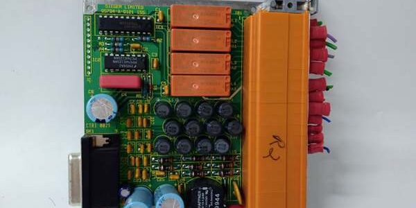
Product Core Brief
- Model: 05704-A-0121
- Brand: Honeywell Analytics (Sieger System 57 Platform)
- Series: 5704 Modular Fire & Gas Detection Rack System
- Core Function: Quad SPDT relay interface card to convert internal gas alarm logic signals into external hardwired outputs for beacons, horns, and ESD interlocks
- Product Type: 4-Channel Safety Relay Output Interface Card
- Key Specs: 4 independent SPDT relays | 5A contact rating | 3U Eurocard rack form factor | Terminal block field wiringNote: Discontinued end-of-life legacy fire/gas hardware, stocked only as unopened New Surplus inventory.
Key Technical Specifications
- Compatible Host Cards: 05704-A-0144 catalytic bead gas control card, 05704-A-0145 4–20mA gas control card
- Relay Configuration: 4× Single Pole Double Throw (SPDT) isolated contact sets
- Contact Switch Ratings: 5A @ 110/250VAC; 5A @ 32VDC resistive load
- Dielectric Isolation: 100 MΩ minimum insulation resistance at 500VDC between rack backplane and field relay terminals
- Mechanical Relay Endurance: Minimum 10 million switch cycles under rated load
- Terminal Block Wire Capacity: Accepts up to 2.5mm² (14 AWG) solid/stranded copper wire
- Rack Form Factor: Standard 3U plug-in Eurocard for 19-inch System 57 subrack chassis
- Backplane Operating Voltage: 18–32VDC nominal 24VDC rack supply
- Ambient Operating Temperature: -40°C to +70°C cabinet ambient
- Hazardous Location Approval: FM Class I Div 2 Groups A/B/C/D cabinet mounting certified
- PCB Protection: Conformal coated to resist corrosive offshore and refinery cabinet atmospheres
- Physical Dimensions: 132mm H × 25mm W × 170mm D; net unit weight 350g
Product Introduction
This plug-in relay card acts as a galvanically isolated bridge between System 57 gas detection logic and site safety actuation hardware. It eliminates the need for auxiliary external relay panels on small to medium fire/gas monitoring racks.Each isolated relay channel can be mapped to low/high gas concentration alarms or fault states from the paired 4-channel gas control card, delivering hard contact signals that comply with site ESD and emergency ventilation interlock requirements.
QA & Testing SOP (Transparency Building)
- Incoming Inspection: Cross-reference serial identifiers against Honeywell OEM production batch logs; inspect PCB for coating delamination, cracked solder joints, bent backplane edge connectors, and damaged terminal block lugs; validate original factory anti-static packaging seal integrity.
- Live Testing: Installed inside a bench System 57 19-inch subrack powered by a Fluke 115 regulated 24VDC supply; mated with a 05704-A-0145 control card to run 24-hour cyclic relay actuation testing with simulated low/high alarm trigger signals injected to all four channels.
- Electrical Testing: Megger insulation resistance test >100MΩ between backplane logic circuits and each relay field terminal; verify each SPDT contact switches cleanly at full 5A AC/DC rated load without chatter.
- Firmware/Config Backup: No onboard programmable firmware storage; capture high-resolution photos of rack backplane channel mapping jumpers for field service reference before bench testing.
- Final QC & Packaging: Attach serialized printed test pass tag; seal unit in foam-lined static-shielded bag to protect edge connector pins and terminal blocks during warehouse storage and transit.
Installation Pitfalls & Guide (Engineer to Engineer)
❗ Firmware Rev Compatibility Risk: System 57 rack firmware V08 and older releases lack full channel fault relay mapping logic; upgrade rack engineering card firmware to V10 or newer before card swap to avoid untriggered external alarm hardware during gas excursion events.❗ Jumper Configuration Loss: Capture high-res photos of backplane channel assignment jumpers on the removed old unit; misconfigured jumpers link alarm signals to incorrect relay outputs and fail site safety interlock response tests.❗ Wiring Incompatibility: This relay card’s backplane pinout does not interchange with 05704-A-0131 16-channel relay expansion boards; cross-substitution without full rack backplane reconfiguration disables all external alarm linkage entirely.❗ Contact Load Miscalculation: Driving inductive solenoid loads above 5A rating creates contact arcing that erodes relay contacts in under 12 months; install external snubber diodes or auxiliary contactors for high-inductance field devices.❗ ESD Component Damage Risk: Ungrounded technicians have destroyed backplane signal optocouplers during rack card swaps; latent ESD damage causes intermittent relay dropout that surfaces after 3–5 weeks of continuous runtime.
4-step replacement guide:
- Pre-install: Activate cabinet LOTO on 24VDC rack power and all external alarm field wiring; secure grounded anti-static wrist strap to rack DIN rail ground lug.
- Removal: Document backplane mapping jumper positions via photo; extract the card from the 3U rack slot, disconnect all field alarm wiring channel by channel from the orange terminal block.
- Install: Seat new hardware fully into matching empty 3U rack slot, replicate all channel mapping jumper settings from reference photos, reterminate field alarm wiring to matching terminal block screw positions.
- Power-on Test: Restore rack and field power; trigger simulated low/high gas alarms via the paired gas control card to confirm each SPDT relay channel energizes external horns, beacons, and interlock valves as configured.
FAQ (Frequently Asked Questions)
Q: Can this relay card pair with single-channel 05701 gas control cards in the same System 57 rack?A: Physically compatible in the subrack, but backplane signal addressing is optimized for 4-channel 5704 series control cards. Pairing with single-channel hardware requires manual jumper reconfiguration for each relay channel to avoid cross-channel alarm misfires.Q: Does the card support hot-swapping while the System 57 rack remains energized?A: The card can be extracted from the live rack slot, but all external field wiring must be fully disconnected first. Live field load disconnection induces inductive voltage transients that damage the onboard optocoupler signal isolation circuits on the PCB.Q: What warranty coverage applies to bench-tested surplus stocked units?A: All inventory units carry a 12-month functional warranty covering factory PCB, relay coil, and backplane optocoupler circuit defects. Damage from inductive load arcing, misconfigured mapping jumpers, or ungrounded ESD handling is excluded from all coverage terms.Q: Is there a direct drop-in modern replacement for this discontinued relay hardware?A: Honeywell’s current-generation fire/gas rack systems use modular relay terminal assemblies with different backplane communication protocols; full rack backplane rework and gas alarm logic revalidation is mandatory, with no unmodified direct swap capability.Q: What fault isolation do the independent SPDT relay channels provide during field wiring shorts?A: Each relay channel uses isolated contact circuits; a shorted external alarm wire only disables one output channel, leaving the remaining three alarm linkage paths fully operational for critical gas hazard alerting.Q: Can multiple gas control cards share a single unit for alarm relay outputs?A: No. Each card is hardwired via the rack backplane to one dedicated 4-channel gas control card only. Additional gas monitoring loops require separate matching relay cards installed in vacant rack slots.Q: Can this relay board switch AC mains lighting circuits directly without auxiliary contactors?A: Only permitted for resistive lighting loads at or below the 5A contact rating. Inductive fluorescent or high-wattage lighting loads create destructive contact arcing and require intermediate auxiliary contactor hardware between the relay card and field lighting fixtures.




