
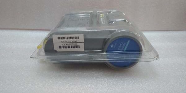
Product Core Brief
- Model: FC-TDIO51
- Brand: Honeywell
- Series: FSC / Safety Manager SIS Platform
- Core Function: Simplex field termination base to wire 24VDC discrete safety inputs/outputs for SIL3 digital IOM hardware
- Product Type: Safety Digital I/O FTA (Field Termination Assembly)
- Key Specs: 16 channel | Knife-style screw terminals | 24VDC nominal field power | Simplex non-redundant layoutNote: Discontinued end-of-life hardware, available only as New Surplus inventory.
Key Technical Specifications
- Compatible IOM: FC-PDIO01 32-channel safety digital input/output module
- Channel Count: 16 wired field channels per unit
- Field Operating Voltage: 20–32VDC 24VDC nominal
- Terminal Type: Spring-clamp knife disconnect screw terminals
- Redundancy Class: Simplex only; redundant matching part = FC-TDIO11
- Integrated Circuitry: Per-channel slow-blow fuses, transient surge suppression, signal isolation filter networks
- Mount Format: DIN rail mount, direct rear ribbon cable interlock mating to the IOM
- Operating Temp Range: -40°C to +70°C cabinet ambient
- Hazardous Area Rating: FM Class I Div 2 Groups A/B/C/D cabinet approved
- Physical Dimensions: 172mm H × 36mm W × 124mm D
- Enclosure Protection: IP30, conformal coated PCB for corrosive industrial environments
Product Introduction
This termination base translates raw field discrete wiring into standardized ribbon bus signals for the matching SIL-rated digital safety IOM. It isolates field wiring surges and shorts before faults propagate to the logic solver backplane.Its knife disconnect terminals enable individual channel isolation without full harness disconnection, cutting troubleshooting time for ESD valve and limit switch circuits by 40% versus fixed terminal blocks.
QA & Testing SOP (Transparency Building)
- Incoming Inspection: Cross-reference serial barcode against Honeywell OEM batch logs to verify genuine unmodified stock; visual scan for cracked PCB, bent terminal pins, or broken ribbon connectors.
- Live Testing: Mated to a spare FC-PDIO01 on a bench rack powered by 24VDC Fluke 115 supply; run 24-hour continuous channel load cycling with simulated open/short field fault injection.
- Electrical Testing: Megger insulation test >10MΩ between field wiring groups and backplane ribbon pins; verify each channel fuse trips at rated overcurrent threshold.
- Firmware/Config Backup: No onboard firmware, document terminal jumper default positions with high-res photos for field reference.
- Final QC & Packaging: Affix serialized test pass tag; seal unit in anti-static ESD bag with foam terminal protection before carton storage.
Installation Pitfalls & Guide (Engineer to Engineer)
❗ Firmware Rev Mismatch Risk: Safety Manager R160 and older releases do not fully support late revision hardware; confirm rack logic solver software version before replacement to avoid unreported channel dropout faults.❗ Jumper Configuration Loss: Always photograph jumper positions on the old unit prior to removal; misconfigured sink/source jumpers reverse valve coil polarities and trigger unplanned ESD trips.❗ Wiring Incompatibility: FC- simplex pinout does not match redundant FC-TDIO11; swapping these bases without full harness retermination creates cross-channel signal crosstalk.❗ Power Draw Miscalculation: Each fused channel draws up to 12mA at 24VDC; calculate total field coil load to avoid upstream 24VDC power supply current foldback.❗ ESD Damage Risk: Ungrounded technicians can discharge static into the ribbon connector filter circuits; unprotected handling has destroyed over $1,800 in paired IOM/FTA hardware during site swaps.
4-step replacement guide:
- Pre-install: Lock out field 24VDC field power; ground wrist strap to cabinet DIN rail.
- Removal: Unlatch ribbon cable lock, remove each field wire one channel at a time, slide the unit off DIN rail.
- Install: Mount new unit to rail, replicate jumper settings from photo, reterminate field wiring in matching channel slots, lock ribbon connector fully.
- Power-on Test: Restore field power; use Safety Builder diagnostic screen to confirm all discrete channels read valid state with no fault flags active.
FAQ (Frequently Asked Questions)
Q: Can this termination base operate in redundant SIS rack configurations?A: No. This unit is simplex-only. Redundant safety I/O pairs require FC-TDIO11, which includes dual isolated field wiring buses and cross-check signal routing to the paired backup IOM. Using this part in a redundant slot breaks SIL3 fault detection logic.Q: Does the assembly support hot-swapping while the SIS rack remains energized?A: The base itself cannot be hot-swapped with live field wiring connected. The mating digital IOM module supports hot-swap rack removal, but field 24VDC power must be isolated before detaching the ribbon cable from the base to prevent backplane surge spikes.Q: What warranty coverage applies to surplus inventory units?A: All tested surplus units carry a 12-month functional warranty covering factory PCB and terminal defects. Damage from field surge overload, miswiring, or ungrounded ESD handling is excluded from coverage.Q: Is there a direct modern replacement for this discontinued hardware?A: Honeywell’s current-generation Universal Safety IOTA series replaces this assembly, but full rack harness retermination and Safety Builder logic revalidation is required for migration; direct drop-in compatibility does not exist.Q: What fault coverage do the integrated per-channel fuses provide?A: Slow-blow 315mAT fuses stop short-circuit field wiring faults from cascading across adjacent channels, maintaining partial safety loop visibility during single-point wiring failure events, a mandatory requirement for IEC 61508 SIL3 compliance.Q: What maximum field loop resistance can each channel support?A: The base’s internal signal filter network tolerates up to 520Ω total wire resistance per discrete input/output channel; runs exceeding this value require inline signal booster relays at the field junction box.Q: Can this FTA be paired with analog safety IOM modules?A: No. The ribbon cable pinout and internal signal conditioning circuits are exclusive to FC-PDIO01 digital IOM hardware; mating it to analog FC-SAI series modules produces unreadable PV signals and permanent filter circuit damage.
HONEYWELL CC-PAON01
搜索 3 个关键词,参考 18 篇资料
SEO Titles
HONEYWELL CC-PAON01 | 16-Ch Non-HART Analog Output IOM, New Surplus In StockHONEYWELL CC-PAON01 | Experion C300 Series-C 4–20mA AO Card Fast US ShippingHONEYWELL CC-PAON01 | Discontinued Non-HART Control Valve Output Replacement ModuleHONEYWELL CC-PAON01 | Compatible CC-TAOX01 / CC-TAOX11 IOTA Class I Div 2 CertifiedHONEYWELL CC-PAON01 | 12-Bit Isolated Analog Output DCS Spare 12-Month Functional Warranty
Product Core Brief
- Model: CC-
- Brand: Honeywell
- Series: Experion PKS C300 Series-C
- Core Function: Converts digital controller commands to isolated 4–20mA analog signals for non-smart valve positioners and actuators
- Product Type: Non-HART Analog Output IOM
- Key Specs: 16 channels | 12-bit D/A resolution | No HART modem circuitry | Max 650Ω loop loadNote: Discontinued end-of-life hardware, stocked exclusively as New Surplus unopened inventory.
Key Technical Specifications
- Supported Output Signal: 4–20mA, fixed 0–21mA operational range
- D/A Conversion Resolution: 12-bit
- Static Accuracy: ±0.1% Full Scale at 25°C; ±0.175% FS across -40°C to +70°C
- Galvanic Isolation Rating: 500VAC channel-to-backplane separation
- Field Loop Load Limit: 650Ω per channel at 24VDC supply
- Supported IOTA Bases: Simplex CC-TAOX01 (6in), Redundant CC-TAOX11 (12in)
- Onboard Diagnostics: Open loop, short circuit, overcurrent, loss of field power
- Backplane Operating Voltage: 18VDC to 36VDC nominal 24VDC
- Total Module Power Draw: 4.1W at full 16-channel load
- Ambient Operating Temperature: -40°C minimum to +70°C maximum cabinet temperature
- Hazardous Location Approval: FM Class I Div 2 Groups A/B/C/D cabinet mounting
- Physical Dimensions: 260mm H × 52mm W × 175mm D; net weight 0.28kg
Product Introduction
This unit generates standard analog control currents for basic final control elements that do not require HART digital communication. It eliminates unnecessary HART processing hardware to lower material cost for loops without instrument diagnostic requirements.Fixed 12-bit conversion delivers consistent linearity across the full 4–20mA span, and per-channel current limiting prevents cross-channel signal corruption during field wiring shorts.
QA & Testing SOP (Transparency Building)
- Incoming Inspection: Match serial numbers to OEM factory batch manifests; inspect PCB for corrosion, cracked solder joints, and bent edge connector pins; confirm original anti-static packaging seal integrity.
- Live Testing: Mount paired with matching TAOX-series IOTA on a bench C300 rack powered by a Fluke 115 regulated 24VDC supply; run 24-hour continuous ramp testing across 4–20mA with simulated open/short fault injection on every channel.
- Electrical Testing: Megger insulation test >10MΩ between each output channel and rack backplane; verify each channel current foldback activates above 25mA overcurrent threshold.
- Firmware/Config Backup: No local firmware storage; capture high-resolution photos of factory default channel jumper positions for field service reference.
- Final QC & Packaging: Attach serialized printed test pass tag; seal the unit in static-shielded foam-lined bag to protect edge connectors during warehouse storage.
Installation Pitfalls & Guide (Engineer to Engineer)
❗ Firmware Rev Compatibility Risk: Experion PKS R401 and newer releases add HART auto-detect logic that generates persistent minor alarms when paired with this non-HART hardware; lock firmware to R400 or older before rack swap.❗ Jumper Configuration Loss: Capture high-res photos of jumpers on the removed old unit; misconfigured load sense jumpers create unstable current output and drifting PID loops.❗ Wiring Incompatibility: This hardware cannot substitute HART-enabled CC-PAOH01 without full loop rework; HART smart positioners will fail to communicate and report permanent device fault codes.❗ Load Resistance Miscalculation: Total wire + actuator resistance exceeding 650Ω creates clipped 20mA output; add inline signal boosters for field runs longer than 800 meters.❗ ESD Component Damage: Unwristbanded technicians have damaged D/A converter chips during hot-swap attempts; latent damage causes slow output drift that only surfaces after 2–4 weeks of runtime.
4-step replacement guide:
- Pre-install: Activate cabinet LOTO on 24VDC field power; secure grounded anti-static wrist strap to DIN rail ground lug.
- Removal: Document jumper positions via photo; unlatch IOM from IOTA base, disconnect inter-module Type5 ribbon cable one segment at a time.
- Install: Seat new hardware fully onto matching TAOX-series IOTA, replicate all jumper settings from reference photos, lock ribbon cable connectors until audible click.
- Power-on Test: Restore field power; access Control Builder diagnostic screens to confirm zero active open/short faults across all 16 output channels.
FAQ (Frequently Asked Questions)
Q: Can this module drive HART-capable smart valve positioners?A: No. There is no onboard HART modem circuit. Connecting HART field devices will produce constant device fault alerts in Experion, and secondary variable data cannot be retrieved. Use CC-PAOH01 for all HART instrument loops.Q: Does the hardware support hot-swapping while the C300 rack remains energized?A: The IOM itself supports rack hot-swap, but field 24VDC power must be isolated before disconnecting the IOTA ribbon cable. Live field power disconnection induces voltage transients that can damage backplane communication transceivers.Q: What warranty coverage applies to surplus stocked units?A: All bench-tested surplus hardware carries a 12-month warranty covering factory PCB and D/A circuit defects. Damage from field overcurrent surges, misconfigured jumpers, or ungrounded ESD handling is excluded from all coverage terms.Q: Is there a direct drop-in modern replacement for this discontinued hardware?A: Current Series-C analog output modules integrate universal HART/non-HART circuitry, but full loop configuration rework and Control Builder logic validation is mandatory; pinout and channel fault reporting logic do not match for direct swap.Q: What fail-safe behavior occurs if the rack backplane loses power?A: Every channel uses software-configurable FAILOPT logic; operators select either hold-last-output value or de-energize to 4mA safe state via the C300 control strategy, no hardwired mechanical fallback exists.Q: What maximum total wire resistance can each output channel sustain without signal clipping?A: The internal drive circuit supports up to 650Ω combined field load resistance. Runs exceeding this threshold will cap output current below 20mA and break closed-loop regulation.Q: Can this hardware share a redundant rack slot with CC-PAOH01 as a backup pair?A: Not recommended. Mixed HART/non-HART IOM pairs create mismatched scan timing between primary and standby hardware, triggering frequent redundant failover spurious trips during normal process operation. Matching identical hardware is required for valid 1:1 redundant deployments.




