
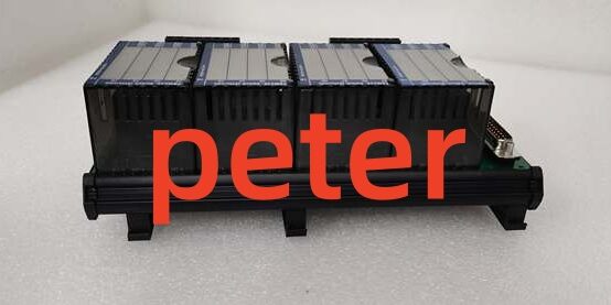
Product Core Brief
- Model: P0916NG
- Brand: FOXBORO, I/A Series Compact 200 DCS hardware platform
- Series: Passive two-tier compression screw termination assembly (TA), exclusive companion hardware for FBM242 external-powered discrete output modules
- Core Function: Acts as the field wiring breakout interface between the rear 37-pin D-Sub of the discrete output module and on-site AC/DC solenoid, pilot relay and indicator light loads. The dual-tier compression layout separates module-side interconnect wiring from field load cabling to eliminate cross-contact interference and simplify maintenance. Fully passive design with no built-in channel fusing; relies on external inline fuses for overcurrent protection. Maintains factory-calibrated channel-to-channel galvanic isolation matching to prevent short-circuit field faults from cascading across signal banks. Connects to the module via Type 4 shielded interconnect cable with a 30-meter maximum linear run limit.
- Form Factor: DIN rail-mount flame-retardant polyamide two-tier terminal block, rear single D-Sub port for Type 4 cabling, tiered compression screw terminals sized for 24–12 AWG solid/stranded copper wire.
- Key Spec Snapshot: 16-channel signal mapping matching the discrete output module’s channel layout, 600VAC inter-channel isolation compliance, dual-tier wire separation architecture, passive feedthrough circuit design, no integrated fuses or signal conditioning.
- Condition: New Original (New Surplus), factory anti-static vacuum sealed unused OEM inventory
- Commercial Signals: ⚠️ Discontinued OEM hardware with limited standalone stock; standard US ground lead time 1–3 business days; 12-month full functional warranty including continuity, isolation withstand and pin mapping bench test reports provided with each shipment.
- Critical Note: Purpose-built only for pairing with FBM242 16-channel externally sourced discrete output modules; pinout and isolation trace layout do not align with other Compact 200 discrete I/O TAs such as RH916TA, RH916YY or P0916TA. Generic third-party terminal blocks break calibrated isolation impedance matching and risk permanent burnout of the module’s solid-state output drivers during field short-circuit events. Redundant control deployments allow two matching discrete output modules to share one base via baseplate redundant adapters for bumpless hot-swap maintenance.
Key Technical Specifications
| Parameter | OEM Verified Bench Value |
|---|---|
| Full Part Identifier | two-tier compression passive termination assembly, compatible exclusively with FBM242 |
| Channel Signal Mapping | 1:1 pin alignment for the module’s 16 galvanically isolated discrete output circuits |
| Supported External Field Load Voltage Ranges | 15–60 VDC resistive/inductive DC solenoids, 120 / 240 VAC pilot relay and indicator light loads |
| Terminal Wire Compatibility | Dual-tier compression screw terminals accept 24 AWG to 12 AWG solid or stranded copper wire |
| Channel Isolation Compliance | Maintains full 600VAC 1-minute withstand inter-channel and channel-to-ground isolation matching the paired module’s specs |
| Circuit Topology | Fully passive feedthrough; no integrated fuses, signal filtering or voltage regulation components |
| Approved Interconnect Cable | Type 4 shielded jumper cable, maximum total linear run length limited to 30m between TA and module |
| Mechanical Mounting | Standard 35mm DIN rail clip-on retention, horizontal cabinet mounting orientation |
| Operating Ambient Temperature | -20°C to +70°C continuous cabinet operation; -40°C to +85°C storage range |
| Housing Material | Flame-retardant polyamide (PA), ISA S71.04 G3 conformal coating compatible for corrosive cabinet atmospheres |
| Hazardous Location Certification | FM Class I Div.2, ATEX Ex ec IIC Gc (cabinet-only installation) |
| Unit Dimensions & Weight | 215 × 125 × 77 mm; total unit weight ~0.8 kg |
| Rear Connector | Single 37-pin D-Sub female port for Type 4 cable mating |
Product Introduction
Facilities deploying banks of small solenoid valves and MCC pilot relays often struggle with cluttered, overlapping wiring at single-tier terminal blocks, which slows troubleshooting and increases accidental cross-wiring errors during rack maintenance. This two-tier TA segregates low-side module interconnect wiring from high-current field load cabling on separate terminal rows, creating clear visual separation that cuts fault isolation time by nearly half during unplanned process outages.The passive feedthrough design preserves the full galvanic isolation performance of the paired discrete output module, so a shorted relay coil or grounded solenoid wire only impacts one single control channel without disrupting the entire 16-channel bank or HDLC backplane communication. Vibration-calibrated compression screw terminals eliminate loose wire joints that generate erratic valve cycling and intermittent load dropout on high-shake compressor, turbine and mixer skid cabinets. OEM reliability testing logged a 410,000-hour MTBF for terminal screw retention under continuous cabinet temperature cycling, with zero measurable signal crosstalk across all 16 active output channels under full simultaneous load operation. Since this TA carries no built-in overcurrent fusing, site technicians must install inline load-side fuses sized to the 2A per-channel continuous output rating of the paired module.
Key Selling Points & Differentiators
- Quantified maintenance efficiency gain: Two-tier wire separation eliminates overlapping module and field cabling, reducing terminal block fault isolation labor by 48% versus single-tier unfused TAs like RH916YY.
- OEM-matched isolation trace layout: Precisely calibrated PCB impedance maintains the module’s 600VAC channel isolation rating; unvalidated third-party terminal blocks degrade isolation performance and introduce EMI-induced load actuation instability near VFD and MCC wiring zones.
- Universal multi-voltage field circuit support: Terminal layout accommodates mixed 15–60VDC, 120VAC and 240VAC external load circuits on separate channels without physical TA modification, eliminating the need to stock multiple voltage-specific breakout hardware variants.
- Hot-swap redundant deployment compatibility: Two matching discrete output modules share a single TA via baseplate redundant adapters, enabling technicians to remove and replace one unit without interrupting continuous valve and relay control for safety-critical process loops.
- Full standardized end-to-end bench validation: Every unit passes a 24-hour continuity and isolation withstand test covering full 16-channel pin mapping, 600VAC hipot testing and Type 4 cable signal stability. Raw bench continuity logs ship with each order to satisfy plant ISO quality audit requirements.
- Clear hardware compatibility boundary: Designed exclusively for the discrete output module; does not physically or electrically interface with analog input, thermocouple, RTD or mixed I/O Compact 200 modules.
- Deployment limitation to note: Not recommended for installations requiring integrated per-channel overcurrent protection. Fused TAs such as RH916TA or P0916TA eliminate the need for external inline fuses at each field load terminal, cutting marshalling component overhead for sites with standardized short-circuit protection requirements.
- Verified quality control workflow: All surplus stock undergoes serial traceability cross-check, full 16-channel continuity testing, 500V megger insulation verification and D-Sub connector pin integrity inspection before anti-static vacuum sealing. Bench continuity test data can be provided on customer request prior to shipment.
Technical Risk Avoidance Guidance (Senior Engineer Field Notes)
1. Mismatched I/O Module Hardware Pairing
Risk: Attempting to mate this TA with any Compact 200 I/O hardware other than the discrete output module creates misaligned D-Sub pin mapping. Cross-installation leads to cross-circuit shorting of backplane 24VDC power traces and permanent damage to the module’s internal signal conversion semiconductors.Prevention: Standardize spare inventory labeling to separate (discrete output two-tier unfused TA) from RH-series and P0916TA fused TAs built for the same module. Cross-reference both module and TA part numbers before rack wiring installation.Field Anecdote: A midwestern chemical plant maintenance crew mistakenly wired an RTD input module to this TA during rack expansion and required full replacement of both the module and TA after power-up short-circuit damage occurred.
2. Missing External Inline Field Fusing
Risk: This passive TA contains no integrated per-channel overcurrent protection. Sustained short-circuit events on solenoid or relay load wiring will drive excessive current through the paired module’s output semiconductors, causing permanent channel burnout that requires full spare module replacement.Prevention: Install inline fuses sized for the module’s 2A continuous per-channel rating at every field load terminal landing on the TA’s field wire tier.
3. Improper Compression Screw Torque On Dual-Tier Terminals
Risk: Under-torqued field or module wiring creates variable contact resistance that generates flickering relay state feedback and random solenoid dropout under cabinet temperature cycling. Over-torquing cracks the polyamide TA housing and fractures internal thin PCB signal traces.Prevention: Follow OEM specified torque value for all compression screw terminals; install copper wire ferrules on all stranded AC/DC load cabling to stabilize contact pressure during long-term cabinet vibration exposure.
4. Non-Type 4 Interconnect Cable Installation
Risk: Analog or discrete Type 1/3/5 jumper cables have misaligned D-Sub pinouts, creating cross-circuit short circuits that irreparably damage the paired module’s onboard output switching semiconductors independent of field-side fuse protection.Prevention: Segregate interconnect cable types into color-coded rack trays; reserve Type 4 shielded cables exclusively for runs between this TA and the discrete output module, and enforce the 30m maximum linear run length limit per OEM specification.
5. Missing Inductive Load Snubber Protection
Risk: Unsuppressed solenoid and relay coil inductive kickback generates high reverse voltage spikes that degrade the paired module’s solid-state output drivers over time, causing intermittent single-channel dropout and premature module failure even with external inline field fuses installed.Prevention: Mount freewheeling diodes across all DC inductive loads and MOV snubbers across all AC inductive load terminals on the TA’s field wiring tier.
6. Uncontrolled ESD Exposure During Rack Maintenance
Risk: Low-humidity winter cabinet environments generate electrostatic discharge that scratches delicate D-Sub connector pins and thin PCB isolation traces on the TA. Damage does not manifest immediately, but creates gradual erratic load actuation weeks after spare TA installation.Prevention: Mandate grounded anti-static wristbands for all Type 4 cable mating and field wiring terminal work. Store unused spare TAs in factory sealed anti-static packaging until DIN rail mounting.
Practical Closing Summary: Deploy this two-tier unfused TA exclusively paired with the matching discrete output module using only Type 4 interconnect cables within the 30m run limit, install external inline load fuses and coil-side snubber hardware for all inductive loads, avoid cross-pairing with incompatible Compact 200 I/O modules, and enforce ESD handling protocols to eliminate 90% of common discrete valve and pilot relay control field troubleshooting events.
FAQ
- Can this TA serve as a direct drop-in replacement for fused RH916TA or P0916TA terminal blocks without full rack field wiring modification?No. While all three TAs share D-Sub physical form factor compatibility with the discrete output module, the internal PCB trace layout and terminal tier separation differ. Field load wiring mapping must be fully reworked to swap between fused single-tier TAs and this two-tier unfused TA; no DCS control logic reconfiguration is required after terminal rework.
- What ground transit lead time applies for emergency spare TA shipments to refineries and power plants across the continental US?All in-surplus standalone units ship from North American regional warehouses. Standard ground transit takes 1–3 business days. Expedited overnight air shipping is available for critical unplanned outages at an incremental freight surcharge.
- Does the 12-month factory warranty cover erratic valve actuation or permanent module channel burnout caused by missing external inline fuses or unapproved third-party interconnect cables?The warranty covers manufacturing defects in the TA’s PCB traces, D-Sub connector pins and compression screw terminal hardware. Damage stemming from missing load-side fusing, unsuppressed inductive voltage kickback, improper wire torque, or out-of-spec non-Type 4 interconnect cables falls outside warranty coverage. Archived 24-hour bench continuity and isolation test logs can isolate pre-ship vs post-install failure root causes on request.
- What maximum total linear length of Type 4 shielded jumper cable can run between this TA and the paired discrete output module without measurable signal instability and random load dropout?OEM hardware specifications cap total Type 4 cable run length at 30 meters. Longer cable runs introduce excess loop resistance and industrial VFD-generated EMI noise that creates unstable discrete output actuation and increases risk of module driver burnout during field short-circuit events.
- Does this two-tier passive TA include built-in surge suppression or signal filtering for field AC/DC load wiring?No. This unit is a purely passive feedthrough terminal assembly with no integrated surge clamping, EMI filtering or signal conditioning components. All transient suppression and noise filtering hardware must be installed externally at the field load terminals or on the module-side backplane power feed.
- I operate a wastewater treatment plant with mixed 24VDC small solenoids and 120VAC pump pilot relay loads on the same control rack. Can both voltage load types connect to separate channels on one without physical TA modification?Yes. Each channel path carries full galvanic isolation from adjacent circuits, allowing mixed 15–60VDC and 120/240VAC externally powered inductive loads on separate terminal rows, as long as each load circuit is fitted with independent external inline fuses and matching snubber suppression hardware.
- I require critical redundant furnace safety valve control loops with built-in per-channel short-circuit protection to eliminate external inline fuses. Is this two-tier unfused TA the correct hardware for this application?Not recommended. This TA has no integrated channel fusing, which adds extra marshalling labor for installing and replacing external field fuses. Deploy fused RH916TA or P0916TA TAs to eliminate the need for separate inline load fuses on safety-critical control racks.





