
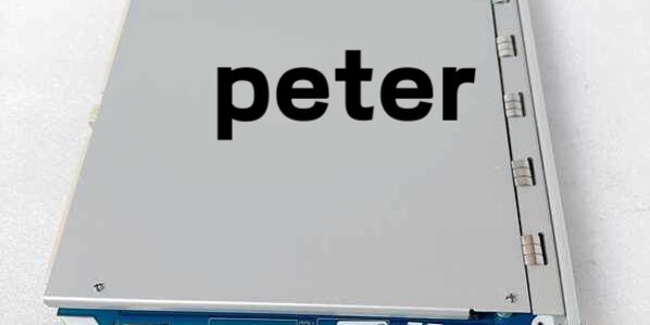
Product Core Brief
- Model: 3500/22M 288055-01
- Brand: Bently Nevada (Baker Hughes)
- Series: 3500 Machinery Protection TSI Rack System
- Core Function: Rack master TDI that aggregates all monitor data, stores fault waveforms, and communicates with System 1 / plant DCS
- Product Type: Single-slot hot-swappable rack master transient data interface
- Key Specs: 10/100 Ethernet + USB-B front ports | 128kHz max waveform sampling | 10.5W max power draw
- Note: Current production active, new surplus and OEM replacement units available.
Key Technical Specifications
- Mandatory installation slot: Rack Slot 1 (adjacent to power supplies)
- Power input: 24VDC rack backplane, maximum 10.5W continuous draw
- Front communication ports: Autosensing 10/100BASE-TX RJ45 Ethernet, USB-B local service port
- Transient sampling speed: Up to 128kHz per active measurement channel
- Onboard storage: Non-volatile flash for timestamped post-fault waveform snapshots
- Isolation rating: 1500VAC galvanic separation between front I/O and rack backplane bus
- Operating temperature range: -40°C to +85°C for conformal coated variants; -30°C to +65°C standard
- Supported protocols: EGD, Modbus TCP, SNTP time sync, proprietary 3500 backplane bus
- Physical dimensions: 266mm H × 72mm W × 229mm D, single 3500 rack slot form factor
- Certifications: API 670, CE EMC, UL Class I Div 2, ATEX Zone 2
- Critical safety note: This unit operates outside the hardwired protection relay path; module failure cannot block machinery emergency shutdown trips
Product Introduction
This rack master TDI acts as the central data hub for any 3500 series machinery monitoring chassis, combining legacy RIM rack control and high-speed transient waveform capture hardware into one single slot component. It polls every vibration, overspeed, and temperature monitor card to compile steady-state trending data for DCS historians.Its primary field value is onboard fault waveform storage. After an unplanned machine trip, technicians retrieve high-resolution vibration snapshots to pinpoint root bearing or rotor damage without external standalone data loggers.
QA & Testing SOP (Transparency Building)
- Incoming Inspection: Cross-reference serial numbers against OEM production databases to flag counterfeit hardware. Complete physical audit of PCB traces, front port pins, and locking key switch; document all cosmetic defects with high-res photos.
- Live Power-On Testing: Mount the device into a calibrated test 3500 rack powered by a 24VDC Fluke 115 supply. Maintain continuous 24-hour load test with full rack channel simulation to validate steady power draw and Ethernet link stability.
- Electrical Isolation Testing: Use a megohmmeter to verify >10MΩ insulation resistance between Ethernet signal lines and rack ground; confirm no leakage current across isolated circuit boundaries.
- Firmware & Config Backup: Flash the latest compatible OEM firmware revision, record version number, and back up a blank rack configuration file to offline storage. Capture LED state behavior during full rack scan cycles for baseline comparison.
- Final QC & Packaging: Perform a manual waveform capture trigger test to confirm flash memory writes data correctly. Place the unit in anti-static foam, attach a serialized QC tag with test timestamp, and seal in ESD shielding bags for shipment.
Installation Pitfalls & Guide (Engineer to Engineer)
❗ Firmware Rev Mismatch Risk: Mismatched rack monitor firmware will trigger permanent CONFIG fault LED states and block backplane data polling. Always export the existing rack firmware revision set before swapping the module; never load mismatched mixed-revision firmware stacks.❗ Missing Configuration Backup Risk: If no rack config file is saved prior to replacement, all vibration alarm thresholds and waveform capture triggers revert to factory defaults, creating blind unprotected machinery operating conditions.❗ Single-Ended Ground Violation Risk: Running Ethernet cable shield ground at both the rack and plant switch creates ground loop current that corrupts EGD data frames, triggering intermittent full rack tag dropout during VFD startup transients.❗ ESD Damage Risk: Ungrounded field tools discharge static through front USB/Ethernet ports, destroying internal CPU circuits; replacement PCB repairs exceed $1,800 OEM labor cost.❗ Slot Placement Error Risk: Installing the unit in any slot other than Slot 1 disables rack-wide time synchronization and waveform capture functions entirely.
4-Step Replacement Guide
- Pre-install: Ground yourself via wrist strap, photograph front LED status of the old unit, export full rack configuration and record active firmware versions.
- Removal: Unlock front key switch, pull the module extraction levers to release backplane contact pins, slide the unit straight out of Slot 1 without twisting the PCB edge connector.
- Install: Slide the new unit fully into Slot 1, squeeze extraction levers to lock backplane contacts, rotate the front key switch to the unlocked operational position.
- Power-on Test: Restore rack power, upload the saved rack configuration file, trigger a test Alert alarm on a vibration channel to confirm waveform storage and continuous DCS tag readback.
FAQ (Frequently Asked Questions)
Q: Can this unit hot-swap while the 3500 rack remains energized?A: Yes, the hardware supports live hot-swap without full rack power loss. The critical protection relay circuits on all monitor cards remain active during swap, so machinery safety shutdown logic stays intact.
Q: What warranty coverage comes with surplus replacement stock?A: Standard 12-month functional warranty covering internal PCB communication and storage circuits; cosmetic surface scratches and wear marks are excluded from warranty claims. OEM factory-new units carry the full 36-month manufacturer warranty.
Q: Is this hardware interchangeable with the older 138607-01 TDI variant?A: No. The two assemblies use different flash memory sizing and backplane handshake firmware. The older unit cannot support high-channel compressor rack waveform capture loads, and cross-installation generates persistent backplane communication faults.
Q: Will losing power erase stored transient fault waveforms on the device?A: No. All waveform snapshots write to non-volatile onboard flash memory; power cycles do not delete historical fault event data stored locally.
Q: Does this unit require an optional channel disk to capture dynamic vibration waveforms?A: Static steady-state trending operates without the disk. High-speed dynamic waveform capture for fault diagnostics requires the OEM channel enabling disk accessory installed on the PCB.
Q: Can I use this unit without connecting the front Ethernet port to a plant control network?A: Yes. Local USB-B connection to a field laptop supports all configuration upload/download and waveform export functions without active Ethernet LAN wiring. Real-time DCS trending will be disabled until Ethernet connectivity is restored.
Q: Does this module participate in machinery safety shutdown protection logic?A: It does not. All overspeed, vibration, and temperature relay trip circuits run independently on each monitor card. Faults on the device cannot disable hardwired emergency shutdown interlock functionality.




