
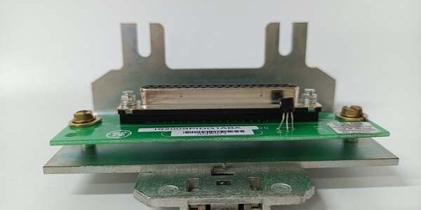
Component Snapshot At-a-Glance
- Model: IS400JPDDG1A (PPDA I/O Pack Power Distribution Module)
- Alt. P/N: IS400JPDEG1A (24/48V battery feed variant, output fuse sizing & connector pinout non-interchangeable, no drop-in swap)
- Product Series: GE Speedtronic Mark VI / Mark VIe gas/steam turbine control cabinet PDM power architecture
- Hardware Type: Vertical bracket-mounted DC fused power distribution printed circuit board
- Key Feature: Dual redundant 24VDC input filtering, three independent fused 15A output branches, built-in solid-state overcurrent cutoff, 50-pin diagnostic header for I/O pack telemetry
- Primary Field Use: Distribute clean fused 24VDC power to Mark VIe analog/digital I/O packs, exciter I/O boards, and communication modules in combined-cycle and steam turbine control MCC racks.
Hard-Numbers: Technical Specifications
- Protocol Support: No digital control bus; passive power distribution with hardwired discrete fault feedback to local DI terminals
- Port Count: Dual 6-pin Mate-N-Lok DC input harness (JPS1/JPS2); three 4-pin fused output connectors (JFA/JFB/JFC); 50-pin top/bottom diagnostic header; front PWR/FAULT LED indicators
- Baud/Data Rate: N/A, purely passive power conditioning hardware
- Operating Temperature: 0°C to +65°C standard unit; coated factory variant rated -25°C to +70°C non-condensing turbine cabinet duty
- Isolation Rating: 1500VAC dielectric isolation between dual input power feeds and each fused output branch
- Power Draw: Max 8.5W idle consumption; dual input range 18–36VDC nominal 24V control supply
- Fuse & Load Ratings: Each JFA/JFB/JFC output fused 15A slow-blow; total combined board continuous load 30A max
- Internal Protection: EMI LC input filter, reverse polarity blocking diode, solid-state overcurrent cutoff, thermal shutdown at +75°C internal temp
- Physical Mount: Vertical metal bracket cabinet mount; weight 0.6kg; IP20 enclosed PCB housing
- Certifications: CE industrial EMC, UL 508, ATEX Zone 2 non-incendive for turbine control rooms
The Real-World Problem It Solves
Daisy-chaining raw 24VDC cabinet supply straight to I/O packs creates unfiltered voltage transients from turbine VFD drives. A single shorted I/O channel pulls down an entire rack of control hardware without branch-level fuse protection, triggering full turbine derate or emergency trip.Separate small DIN fuse blocks add dozens of loose wire splices under cabinet vibration; those splices corrode in salt fog offshore rigs, developing high-resistance hot spots that burn terminal lugs mid-unit run.Where you’ll typically find it:
- Combined-cycle gas turbine Mark VIe main control cabinets feeding ERIO, SPID, and analog I/O VME packs
- Steam turbine EX2100 excitation racks supplying isolated DC power to excitation regulator mixed I/O boards
- Offshore FPSO Zone 2 turbine control rooms using coated IS400JPDDG1A hardware to block hydrocarbon condensation and salt fog PCB corrosionDual redundant filtered power inputs eliminate single feed loss downtime, three isolated fused branches contain short circuits to one I/O group only, and integrated diagnostic header lets techs pull real-time load voltage/current readings without breaking live wiring.
Hardware Architecture & Under-the-Hood Logic
This is a passive power conditioning board with no microprocessor; it only filters, splits, and fuses rack DC supply for downstream I/O packs. Internal LC filtering suppresses VFD noise before power reaches sensitive analog and communication I/O hardware.
- Dual independent JPS1/JPS2 24VDC input harnesses feed separate EMI LC filter banks; internal OR diode circuit provides seamless automatic switchover if one rack power supply fails.
- Filtered common DC bus splits to three isolated output circuits; each branch carries dedicated 15A slow-blow fuse and independent solid-state current-limit cutoff.
- Bidirectional TVS surge suppressors on every JFA/JFB/JFC output absorb lightning and inductive kickback transients from long field I/O wiring runs.
- 50-pin top/bottom diagnostic header taps input voltage, each branch output voltage, and internal PCB temperature signals; hardwired to cabinet discrete input cards for DCS fault alarming.
- Front dual LED status: steady green = both input feeds active, all output fuses intact; flashing red = blown branch fuse, input undervoltage, or internal thermal overtemp shutdown.
- Conformal coated PCB variants seal filter inductors, fuse holders, and DC bus traces against unconditioned cabinet dust, temperature cycling, and offshore salt fog exposure.
Field Service Pitfalls: What Rookies Get Wrong
Dual-End Grounding DC Input & Output Harness Shielded Cables
New techs ground DC power cable shield braid at both IS400JPDDG1A terminal connectors and main rack power supply marshalling panels. Turbine ground grid potential differences create circulating ground loop current, introducing AC ripple noise that distorts analog I/O readings and triggers random communication board timeouts.Field Rule: Terminate all DC power harness shield braid only at the main turbine rack chassis ground stud; fully tape and isolate shield conductors at the JPDDG1A board connector ends.
Substituting IS400JPDEG1A Battery Feed Board In Place Of IS400JPDDG1A
Field crews swap spare JPDEG1A battery distribution hardware into main control rack slots. JPDE’s 48V input rating and mismatched 7A branch fuses cannot support standard Mark VIe I/O pack 24V load draw; constant overcurrent tripping cuts power to critical turbine regulation I/O.Quick Fix: Strict part number matching for standard 24V control I/O racks: deploy only IS400JPDDG1A. Reserve IS400JPDEG1A exclusively for battery-backed UPS auxiliary power distribution cabinets.
Overloading Single 15A Output Branch With Multiple High-Draw I/O Packs
Techs stack 4+ heavy analog/excitation I/O packs onto one JFA/JFB/JFC fused branch, exceeding the 15A continuous rating. Sustained overcurrent blows branch fuses mid-generator load swing, dropping valve position feedback and risking unstable turbine speed regulation.Field Rule: Balance I/O pack loads evenly across all three output branches; clamp meter each branch steady-state draw post wiring to stay under 12A continuous operating margin.
Commercial Availability & Pricing Note
Please note: The listed price is for reference only and is not binding. Final pricing and terms are subject to negotiation based on current market conditions and availability.




