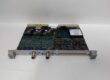
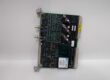
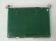
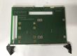
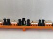
Component Snapshot At-a-Glance
- Model: PS8310 (market standard part number 8310)
- Alt. P/N: 8310N = conformal coated offshore harsh environment variant
- Product Series: Triconex Tricon Triple Modular Redundant SIS Platform
- Hardware Type: Chassis left-slot rack-mount AC/DC universal power supply module
- Key Feature: 175W continuous output, dual universal input, hot-swap, parallel 1oo2 redundant capable, hardwired fault relay contacts
- Primary Field Use: Converts plant AC/DC mains to regulated 6.5VDC backplane power for all Tricon MP, analog/digital I/O TMR modules in safety shutdown racks.
Hard-Numbers: Technical Specifications
- Protocol Support: No data protocol; backplane power distribution + TriBus diagnostic fault reporting to main processors
- Port Count: Rear terminal block for mains input, fault alarm relay contacts; backplane edge connector for 6.5VDC distribution
- Input Range: 90–264VAC 47–63Hz OR 100–140VDC dual universal input
- Operating Temperature: 0°C to +60°C operational; -40°C to +85°C storage
- Isolation Rating: 1500VAC galvanic isolation between mains input and low-voltage backplane circuits
- Power Draw Input: Max 2.8A @ 120VAC; max 2.1A @ 125VDC
- DC Output Rating: 6.5VDC ±1% regulation, 27A continuous, total 175W rated
- Hold-Up Time: Minimum 20ms output hold during input power loss
- Protection Circuits: Overvoltage, overcurrent, short-circuit, thermal shutdown, input surge EMI filtering
- Alarm Relay Contact Rating: 1A @ 120VAC dry SPDT fault contacts
- Internal Thermal Trip: 83°C internal threshold triggers overtemp warning
- Hot-Swap Capable: Yes, built-in hold-up capacitors maintain backplane voltage during live replacement
- Certifications: IEC 61508 SIL3, ATEX Zone 2, UL, CE, ISA-84 compliant
- Dimensions (H×W×D): 406mm × 33mm × 410mm
- Weight: 1.68kg
The Real-World Problem It Solves
Single power supply layouts create full SIS shutdown risk on supply failure. Unfiltered dirty plant mains inject voltage transients that corrupt TMR processor memory and trigger spurious safety trips. Separate external alarm relays add extra wiring to notify DCS of power faults.Where you’ll typically find it:
- Refinery reactor & distillation unit ESD safety instrumented racks
- Offshore FPSO, drilling rig fire & gas (F&G) high-integrity control cabinets
- Fossil power plant boiler, turbine burner management safety systems
This high-wattage isolated power supply runs in parallel redundant pairs, cleans mains noise, and provides hardwired fault signaling without external auxiliary relays.
Hardware Architecture & Under-the-Hood Logic
Standalone AC-DC power conversion board with no signal processing CPU; parallel load-sharing circuitry allows two PS8310 modules to share full rack load in 1oo2 redundancy.
- Universal AC/DC input feeds multi-stage EMI filter and surge suppression circuits.
- PFC rectifier converts wide-range mains to high-voltage internal DC bus.
- Isolated DC-DC converter generates tightly regulated 6.5VDC for TriBus backplane.
- Current-limiting and thermal protection logic cuts output to protect backplane modules during overload/overheat.
- Onboard fault monitoring logic drives front panel LED status and rear hardwired SPDT alarm relay contacts.
- Hot-swap hold-up capacitors sustain backplane voltage for minimum 20ms during live module removal and insertion.
- Parallel load-sharing circuits balance power draw evenly between dual redundant modules.
Field Service Pitfalls: What Rookies Get Wrong
Techs install only one power module to save rack slots. Single supply setup creates single point of failure, invalidating SIL3 safety compliance.
- Field Rule: All SIL3 safety racks require two modules installed in parallel redundant configuration.
Under-torquing mains terminal lugs causing thermal overheatingLoose AC/DC wiring terminals create high resistance hot spots. Internal temperature climbs above 83°C, triggering persistent overtemp fault alarms and supply derating.
- Quick Fix: Use 14–16AWG stranded copper wire; torque rear terminal screws to 0.9Nm; retorque all power terminals after plant thermal cycling.
Blocking chassis left-side ventilation with dense cable bundlesRouting heavy power cable looms directly against side vents restricts cooling airflow. Sustained high ambient temperature reduces maximum output wattage and shortens service life.
- Field Rule: Maintain minimum 30mm clear airflow space on left and right sides of power slot; separate mains wiring and signal wiring trays.
Commercial Availability & Pricing Note
Please note: The listed price is for reference only and is not binding. Final pricing and terms are subject to negotiation based on current market conditions and availability.