")
Component Snapshot At-a-Glance
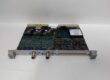
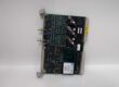
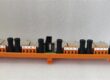
- Model: 3500/50
- Alt. P/N: 133434-01 (standard non-barrier variant)
- Product Series: Bently Nevada 3500 Machinery Protection System
- Hardware Type: Full-height dual-channel rack-mounted tachometer/speed monitor module
- Key Feature: Dual independent sensor inputs, generates rack-wide Keyphasor timing signal for vibration waveform capture
- Primary Field Use: Measures shaft RPM, overspeed, zero-speed, acceleration and rotation direction; supplies reference trigger for all vibration monitor cards in the rack.
Hard-Numbers: Technical Specifications
- Protocol Support: Proprietary 3500 rack backplane bus; configured via 3500 Rack Configuration software
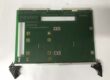
- Port Count: 2 transducer input channels via rear D-Sub I/O card; front panel BNC buffered signal outputs
- Max Input Frequency: 20kHz
- Operating Temperature: -30°C to +65°C operating; -40°C to +85°C storage
- Isolation Rating: 1500VAC galvanic isolation between field sensors and backplane logic
- Power Draw: 24VDC backplane, 5.8W typical load
- Supported Sensors: Eddy current proximity probes, variable reluctance magnetic pickups, voltage pulse inputs
- Input Signal Range: +10VDC to -24VDC internal clamped protection
- Sensor Excitation: 24VDC, max 40mA per channel
- Speed Measurement Range: 0–99,999 RPM
- RPM Accuracy: <100RPM ±0.1RPM; 100–10,000RPM ±1RPM; >10,000RPM ±0.01% full scale
- Recorder Output: 4–20mA proportional RPM signal, 0–600Ω load capacity
- Hot-Swap Capable: Yes, internal hold-up circuit preserves rack bus communication during live swap
- Weight (Front + Rear I/O): ~0.82kg
The Real-World Problem It Solves
Separate single-channel tach cards waste rack slots and cannot supply a shared Keyphasor reference to all vibration monitors. Magnetic pickup signals with low amplitude fail to trigger waveform capture during turbine startup barring.Where you’ll typically find it:
- Combined cycle steam/gas turbine 3500 protection racks for overspeed and startup barring monitoring
- Refinery high-speed centrifugal compressor speed and rotor acceleration safety logic
- Generator and large boiler feed pump vibration diagnostics requiring once-per-rev waveform sync
This dual-channel tach module delivers consistent RPM data and rack-wide timing reference without extra auxiliary interface hardware.
Hardware Architecture & Under-the-Hood Logic
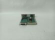
Onboard dedicated 32-bit RISC processor with independent signal conditioning for each channel; requires matching rear tach I/O daughter card for field wiring breakout.
- Regulated 24VDC rack backplane feeds isolated power rails for sensor excitation and signal processing.
- Each channel front-end circuit auto-adjusts threshold for eddy current or magnetic pickup waveforms.
- Zero-crossing detection logic counts gear teeth to calculate real-time RPM and acceleration rate.
- Onboard firmware evaluates user-configured overspeed, zero-speed, reverse rotation and acceleration trip setpoints.
- Synchronized Keyphasor timing pulse broadcast across backplane to all vibration monitor cards for waveform alignment.
- Buffered raw transducer signals route to front-panel BNC ports for bench signal verification with portable analyzers.
- Front panel OK, TX/RX, Bypass LEDs display module health and communication status.
Field Service Pitfalls: What Rookies Get Wrong
Mismatched rear I/O daughter card or loose rear latchesTechs install analog/displacement rear I/O cards to 3500/50 front card or fail to lock rear latches. Pin misalignment triggers constant transducer fault alarms and zero RPM readings.
- Field Rule: Only use dedicated 3500/50 tach rear I/O card; fully seat and lock both latches, tug lightly to eliminate vibration play.
Magnetic pickup wiring without proper signal shieldingUnshielded twisted pair parallel to 480V motor cables induces EMI noise. Signal threshold false triggers produce erratic RPM spikes and false overspeed alarms at steady load.
- Quick Fix: Deploy shielded 2-pair twisted cable; ground shield only at cabinet I/O terminal block, leave machine-side shield floating.
Incorrect teeth-per-rev configuration after gear replacementMaintenance swaps tach gear with different tooth count without updating rack software. RPM calculation reads 2x/3x actual speed, triggering unplanned machine trips.
- Field Rule: Record tooth count on equipment tag; re-download module configuration every time tach gear or probe mounting hardware is modified.
Commercial Availability & Pricing Note
Please note: The listed price is for reference only and is not binding. Final pricing and terms are subject to negotiation based on current market conditions and availability.