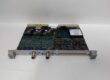
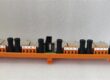
Component Snapshot At-a-Glance
- Model: P0400YD
- Alt. P/N: FBM03
- Product Series: Foxboro I/A Series DCS
- Hardware Type: Multifunction temperature input fieldbus module
- Key Feature: 8 universal channels supporting both thermocouple and RTD sensors
- Primary Field Use: Collect temperature data from process sensors across industrial plant DCS racks.
Hard-Numbers: Technical Specifications
- Protocol Support: I/A Series proprietary fieldbus
- Port Count: 8 analog input channels
- Data Rate: Standard I/A fieldbus communication speed
- Operating Temperature: -20°C to +60°C
- Isolation Rating: 1500V RMS channel-to-backplane isolation
- Power Draw: 24VDC, 10W maximum per unit
- Resolution: 16-bit analog-to-digital conversion
- Sensor Compatibility: J, K, T, E, R, S, B, N thermocouples; Pt100, Ni120 RTDs
- RTD Wiring: Supports 2-wire, 3-wire and 4-wire configurations
- Hot Swap: Functional for live rack replacement
- Accuracy: ±0.1% of full scale reading
The Real-World Problem It Solves
Separate cards for thermocouples and RTDs take extra rack space and add more wiring points. Unisolated inputs pick up electrical noise and ground loops that skew temperature readings.
Where you’ll typically find it:
- Power plant boiler and turbine temperature monitoring racks
- Refinery furnace and reactor sensor banks
- Chemical process units with mixed TC and RTD field sensors
This single module cuts hardware count and blocks common-mode noise for steady temperature readings.
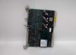
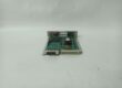
Hardware Architecture & Under-the-Hood Logic
carries a dedicated onboard microprocessor and signal conditioning circuits. It operates independent of the main controller for local signal processing and diagnostics.
- Raw TC or RTD signal enters through field terminal blocks on the module front.
- Surge protection and low-pass filtering clean transient noise from each channel.
- Onboard circuits apply cold junction compensation for thermocouples and fixed excitation current for RTDs.
- 16-bit ADC converts conditioned analog signals into digital data frames.
- Processed data transfers across the isolated barrier to the rack backplane and main DCS controller.
- Module logs channel faults and sends status alerts via fieldbus to the control workstation.
Field Service Pitfalls: What Rookies Get Wrong
Reversed Thermocouple Polarity
Many new technicians fail to check TC lead polarity during wiring. This produces negative readings or locked low values on the DCS display.
- Field Rule: Match positive and negative terminal markings; use color-coded thermocouple extension wire only.
Unbalanced 3-Wire RTD Leads
Uneven resistance between the three RTD wires creates constant offset errors. This issue grows worse with long cable runs.
- Quick Fix: Keep total lead resistance below 50Ω; maintain resistance difference under 0.1Ω across all three conductors.
Running Sensor Cables Alongside Power Wiring
Routing low-level sensor cables parallel to AC power cables introduces 50/60Hz interference. Erratic flickering readings are the main symptom.
- Field Rule: Maintain minimum 30cm separation between sensor cables and AC power lines; use single-point grounding for the I/O rack.
Commercial Availability & Pricing Note
Please note: The listed price is for reference only and is not binding. Final pricing and terms are subject to negotiation based on current market conditions and availability.