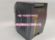
Product Core Brief
- Model: 489-P5-LO-A20
- Brand: GE Multilin
- Series: SR489 Generator Management Relay
- Core Function: Provides protection, metering, control, and diagnostics for small and medium synchronous or induction generators.
- Product Type: Generator Management Relay
- Key Specs: 5 A phase CT secondary | Low-voltage DC control power | 4–20 mA analog outputs | 12 RTD inputs | RS485 Modbus RTU / DNP 3.0
- Condition: New Original / New Surplus
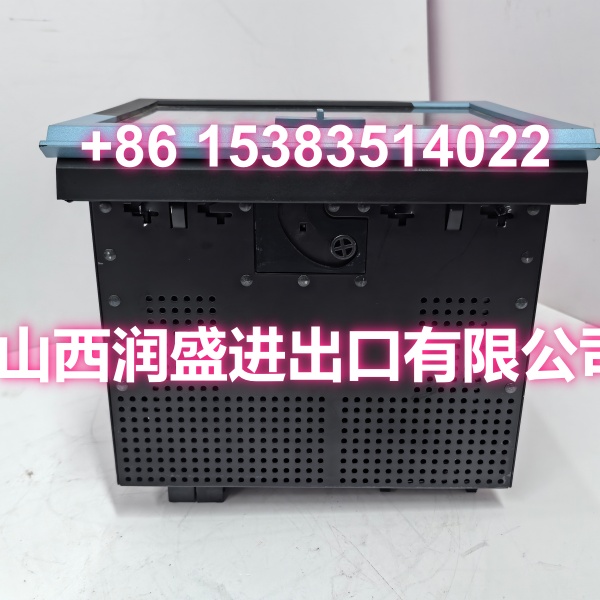
Product Introduction
GE Multilin 489-P5-LO-A20 is a configuration of the SR489 generator management relay, built for small and medium-sized generators in cogeneration, industrial, and utility applications. It provides differential, overcurrent, ground-fault, overload, unbalance, and RTD-based temperature protection, along with metering, event recording, and waveform capture.
The “P5” option indicates 5 A phase CT secondary input, while “LO” denotes a low-voltage DC control power supply. The “A20” option adds isolated 4–20 mA analog outputs for integration with DCS, PLC, or SCADA systems. This model is commonly referenced as SR489-P5-LO-A20-E in field listings. GE Vernova has discontinued manufacturing of the 489 series, with the Multilin 889 named as the alternative.
Key Technical Specifications
| Parameter | Value |
|---|---|
| Manufacturer | GE Multilin |
| Part Number | 489-P5-LO-A20 |
| Product Type | Generator Management Relay |
| Series | SR489 |
| Phase CT Input | 5 A secondary (P5 option) |
| Control Power | Low-voltage DC (LO option), typically 20–60 VDC |
| Analog Outputs | 4 × 4–20 mA isolated (A20 option) |
| RTD Inputs | Up to 12 channels |
| Digital Inputs | 7 assignable inputs |
| Output Relays | 6 Form-C relays |
| Communication | RS485 Modbus RTU, DNP 3.0 |
| Frequency Range | 25 / 50 / 60 Hz |
| Construction | Draw-out panel mount |
| Display | 40-character LCD with status LEDs |
| Operating Temperature | Typically -20°C to +60°C |
Note: Exact control power range and analog I/O assignment should be confirmed against the relay nameplate or setpoint file before commissioning.
Quality Control Process (DYNAMIC GENERATION)
- Front-panel and display check. We verify the LCD, keypad, status LEDs, and relay indicators for full functionality.
- Control power-up test. The relay is energized at its rated low-voltage DC level to confirm stable boot, self-test pass, and no nuisance trips.
- CT and metering validation. With 5 A secondary injection, we verify phase current measurement, voltage inputs, power metering, and ground-fault sensing.
- Analog output verification. All 4–20 mA outputs are checked for correct scaling, linearity, and retransmission response.
- RTD, relay, and communication test. RTD channels are tested with known resistance values, output relays are pulsed under load, RS485 Modbus/DNP3 communication is verified, and the unit is anti-static bagged and foam-packed.
Replacement Pitfall Guide (DYNAMIC GENERATION)
❗ Confirm LO control power before ordering. The LO option typically supports low-voltage DC such as 20–60 VDC. Replacing it with a universal or high-voltage unit without checking the auxiliary supply can damage the relay or prevent startup.
❗ Do not confuse P5 with P1. The 489-P5-LO-A20 uses 5 A phase CTs. A P1 unit requires 1 A CTs and will not read correctly on existing wiring.
❗ Verify analog output assignments. The A20 option provides four 4–20 mA outputs. If the DCS expects specific signals such as current, power, or temperature, the replacement must be reconfigured before commissioning.
❗ Check communication protocol settings. The 489 supports Modbus RTU and DNP 3.0 over RS485. New or replacement relays ship with default addresses and baud rates, so existing SCADA settings must be restored.
❗ Confirm E suffix for conformal coating. Many field units are SR489-P5-LO-A20-E. If the installation environment requires conformal coating, a non-E unit may not be suitable.
Keep these in mind and you’ll cut 90% of rework time.

Compatibility Matrix & Benchmarks
| Original Model | Replacement / Successor Model | Compatibility Level | Migration Notes |
|---|---|---|---|
| GE Multilin 489-P5-LO-A20 | GE Multilin 489-P5-LO-A20 | Direct | Same order code; restore setpoints and communication settings. |
| GE Multilin 489-P5-LO-A20 | GE Multilin -P5-LO-A20-E | Likely Direct | Typical equivalent; verify LO power range and conformal coating. |
| GE Multilin 489-P5-LO-A20 | GE Multilin 489-P1-LO-A20 | Needs Adaptation | CT secondary changes from 5 A to 1 A; CT wiring must be updated. |
| GE Multilin 489-P5-LO-A20 | GE Multilin 889 | Needs Adaptation | Official successor platform; requires full setpoint migration, I/O review, and communication reconfiguration. |
Benchmark highlights
- Draw-out construction for faster replacement and reduced maintenance downtime.
- Supports stator differential, ground-fault, overload, unbalance, and RTD-based thermal protection.
- Four isolated 4–20 mA analog outputs for direct DCS/PLC trending.
- Event records, waveform capture, and IRIG-B time-synchronized logging for faster fault diagnosis.