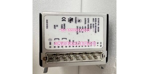
Product Core Brief
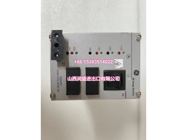
- Model: D20-PS LFDSC143-4000
- Brand: GE Energy / GE Intelligent Platforms
- Series: GE D20 / D200 RTU Family
- Core Function: Chassis power supply module for GE D20/D200 remote terminal units, providing stable DC power to the backplane, processor, communication, and I/O modules.
- Product Type: RTU Chassis Power Supply Module
- Condition: New Original / New Surplus (subject to available stock)
Key Technical Specifications
- Part Number:0-PS
- Platform: GE D20 / D200 Remote Terminal Unit (RTU)
- Function: Primary or redundant power supply for D20/D200 VME chassis
- Input Voltage: Wide-range input suitable for substation DC power systems (confirm exact range from nameplate)
- Output: Regulated DC output to the D20/D200 backplane for processor, communication, and I/O modules
- Protection: Over-voltage, over-current, and thermal protection
- Redundancy: Supports redundant power supply configuration in applicable D20/D200 chassis
- Mounting: Installs in a dedicated power supply slot in the D20/D200 chassis
- Typical Application: Substation automation, SCADA RTU systems, power generation, and industrial process control
Product Introduction (No Fluff)
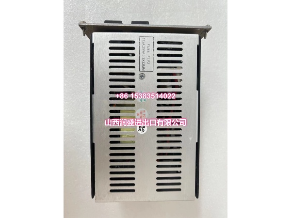
The D20-PS LFDSC143-4000 is a power supply module for the GE D20/D200 remote terminal unit platform. It provides regulated DC power to the chassis backplane, supporting processor boards, communication modules, Ethernet/memory expansion boards, and discrete/analog I/O modules.
The D20/D200 is a field-proven RTU platform widely used in substation automation and SCADA applications. The D20-PS module is designed for industrial and utility environments, with protection features including over-voltage, over-current, and thermal protection to help ensure reliable operation.
In redundant configurations, two D20-PS modules can be installed to provide power supply redundancy. If one supply fails, the other continues to power the chassis, reducing the risk of RTU downtime. The module installs in a dedicated power supply slot in the D20/D200 chassis and does not require complex configuration beyond correct input wiring and status verification.
QA & Testing SOP (Dynamic & Transparent)
Power supplies are critical for RTU availability. Each surplus unit undergoes:
- Part Number Verification: Confirm the label reads D20-PS LFDSC143-4000. Check for GE markings.
- Visual Inspection: Inspect the housing, input/output connectors, mounting hardware, and status indicators for corrosion or damage.
- Connector Check: Verify input and output connector pins are intact and free of oxidation.
- Mechanical Fit Check: Verify the module seats correctly into a compatible D20/D200 chassis power slot.
- Input Voltage Check: Confirm the nameplate input voltage range matches the intended application before energizing.
- Power-Up Test: Apply rated input voltage where test infrastructure is available. Verify output voltage is within specification.
- Status Indicator Check: Observe power-good, fault, and load status indicators where available.
- Load Check: Where possible, verify stable output under light load conditions.
- Packaging: Pack in anti-static bags with foam cushioning. Protect connectors and mounting interfaces during transit.
Installation Pitfalls & Guide (Engineer to Engineer)
Confirm input voltage before wiring. D20 chassis power supplies may be rated for different DC input ranges. Always verify the nameplate rating against the station DC supply before connection.
Do not mix incompatible power supply models. If the chassis uses redundant power supplies, both units should be the same model and rating.
Check redundant configuration. In redundant systems, verify that both power supplies are operational and sharing load correctly before considering the installation complete.
Verify backplane compatibility. Ensure the D20/D200 chassis supports the LFDSC143-4000 power supply variant. Some older or specialized chassis may have different power module requirements.
Monitor status indicators. Power supply faults may appear as chassis-wide issues. Use LED status indicators and RTU diagnostics to confirm healthy operation after installation.
Document installation. Record input voltage, slot position, redundancy status, and any alarm behavior. This simplifies future troubleshooting.
Installation Steps:
- Pre-install: Confirm part number D20-PS LFDSC143-4000 and chassis compatibility. Verify input voltage rating.
- Isolate Power: De-energize the chassis or isolate the power supply circuit before installation.
- Insert Module: Seat the power supply into the correct chassis slot. Verify full mechanical engagement.
- Wire Input: Connect the DC input according to polarity and station wiring standards.
- Commission: Energize the supply. Verify output voltage, status LEDs, and RTU health. If redundant, verify both supplies are operational.
Technical FAQ
1. the ? It is a chassis power supply module for the GE D20/D200 RTU platform, providing regulated DC power to the backplane and installed modules.
2. Is it a processor or I/O module? No. It is a power supply module. Processor, communication, and I/O functions are handled by separate D20/D200 modules.
3. Can it be used in redundant configurations? Yes. The D20/D200 platform supports redundant power supply configurations in applicable chassis.
4. What protection features does it include? It typically includes over-voltage, over-current, and thermal protection.
5. Can I substitute it with another D20 power supply? Only if the replacement is confirmed compatible with the same chassis, input voltage, and output requirements. Do not substitute without verifying the part number and nameplate data.
6. What warranty do you offer on surplus stock? Terms vary by condition and availability. For surplus industrial modules, we typically provide a short functional guarantee. Confirm details at time of order.