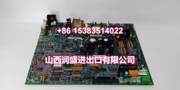
Product Core Brief
- Model: 531X303MCPARG1
- Brand: GE
- Series: GE EX2100 Excitation Control System
- Core Function: Main control processor board for the GE EX2100 excitation regulator, typically used as an M1 or M2 control module to execute AVR/FVR regulation, field control, protection logic, and excitation system diagnostics.
- Product Type: Excitation System Main Control Processor Board / CPU Module
- Key Specs: EX2100 redundant control architecture (M1/M2/C) | Supports AVR, FVR/FCR, gating control, and protection logic | ISBus communication interface
- Condition: New Original / New Surplus
Key Technical Specifications
- Part Number: 531X303MCPARG1
- Product Family: GE EX2100 Digital Static Excitation Regulator
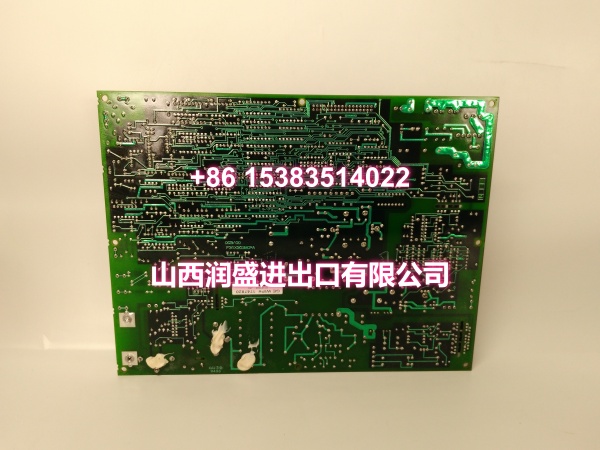
- Board Type: Main Control Processor (MCP) board
- System Role: M1 or M2 redundant control module within the EX2100 core control unit
- Control Functions: Automatic voltage regulation (AVR), field voltage/current regulation (FVR/FCR), SCR gating control, start/stop sequencing, alarm/trip logic, and generator parameter processing
- Redundancy Architecture: Works alongside a second M module and a C (monitor/transfer) module; all three modules vote on I/O decisions for fault tolerance
- Communication Interface: ISBus (GE proprietary high-speed data bus) for internal module communication and data exchange with I/O cards
- Compatible I/O Cards: Interfaces with EMIO, ESEL, EGPA, EPCT, EDCF, EACF, ECTB, and EXTB cards within the EX2100 cabinet
- Typical Applications: Generator excitation control for steam, gas, and hydro turbine units
- Replacement Use: Maintenance spare or emergency swap in existing EX2100 excitation cabinets
Product Introduction (No Fluff)
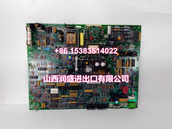
The GE 531X303MCPARG1 is a main control processor board used in the GE EX2100 excitation control system. It serves as an M1 or M2 control module, responsible for executing the core excitation regulation algorithms including automatic voltage regulation, field current control, SCR gating, and protection logic.
This board is a critical component in the EX2100’s redundant control architecture, where two M modules operate in active/standby configuration under the supervision of a C module that monitors health and triggers automatic transfer on fault detection. Because this processor sits at the heart of the excitation control path, matching the exact part number and revision is essential during replacement to avoid configuration mismatch or communication errors.
QA & Testing SOP (Dynamic & Transparent)
For an excitation control processor board, we verify identification, physical condition, and system-level recognition before release.
- Part number verification: Confirm 531X303MCPARG1 on the board label. Record any revision, serial number, or date code markings for traceability.
- Visual inspection: Check the PCB, connectors, edge contacts, fuses, relays, and terminal areas for corrosion, burn marks, cracked components, or mechanical stress.
- Connector and pin inspection: Verify backplane connectors and ribbon-cable interfaces. Bent pins or oxidized contacts can cause intermittent excitation faults.
- System recognition test: Where a compatible EX2100 test rack is available, verify that the board is recognized by the control cabinet without active field gating.
- Firmware/revision check: Confirm that the board revision is compatible with the installed EX2100 software release. Mismatched revisions may require parameter reload or factory support.
- ESD-safe packaging: Ship in anti-static bags with foam protection. Include part number, revision, and inspection status on the shipping label.
Installation Pitfalls & Guide (Engineer to Engineer)
❗ Do not substitute by similar part numbers. EX2100 processor boards have closely related variants (e.g., 531X303MCPALG1, 531X303MCPAYG1, 531X303MCPBCG1). Installing the wrong revision or variant can cause configuration mismatch, ISBus communication errors, or protection logic faults.
❗ Excitation systems are safety-critical. Never replace control processor boards while the generator is online unless the OEM procedure explicitly allows hot replacement. Follow plant switching, isolation, and permit-to-work rules.
❗ Backup parameters before replacement. Record AVR setpoints, FVR/FCR settings, PT/CT ratios, ISBus addresses, and I/O mappings. Some EX2100 parameters may need to be reloaded after processor board replacement.
❗ Verify redundancy status after installation. After seating the new M1/M2 module, confirm that the C module recognizes it, redundancy is restored, and automatic transfer logic functions correctly.
Replacement steps:
- Pre-install: Back up EX2100 configuration, record board slot location (M1 or M2), revision, and alarm history. Isolate the excitation cabinet according to plant procedures.
- Removal: Label all connectors and cables. Remove the board without forcing backplane or ribbon connectors.
- Install: Seat the replacement 531X303MCPARG1 firmly, reconnect wiring, and verify mechanical retention.
- Commissioning test: Restore control power, verify board recognition by the C module, check diagnostics, reload parameters if required, and perform controlled functional tests before returning the generator to service.
Technical FAQ
What is the role of this board in the EX2100 system?
It functions as an M1 or M2 main control processor module, executing AVR/FVR regulation, SCR gating control, protection logic, and generator parameter processing within the EX2100’s redundant control architecture.
Can I use this board as either M1 or M2?
M1 and M2 modules are structurally identical in the EX2100 system, so the same board type can serve in either slot. The C module is structurally different and handles monitoring and automatic transfer.
What happens if I install the wrong revision?
A mismatched revision may cause ISBus communication failures, parameter incompatibility, or unexpected behavior in the redundancy voting logic. Always verify the revision against your installed system documentation.
Is this board still in production?
The EX2100 platform is a legacy system. GE Vernova offers EX2100e as a current excitation solution, while legacy EX2100 hardware is typically maintained through spare parts, retrofits, or system upgrades.
Does this board handle field I/O directly?
No. The MCP board communicates via ISBus with dedicated I/O cards (EMIO, EPCT, EDCF, ECTB, EXTB, etc.) that handle field signal acquisition and output execution.