Product Core Brief
- Model: 531X303MCPBBG1
- Brand: GE / GE Industrial Systems
- Series: GE Speedtronic Mark VI Turbine Control System
- Core Function: Processor node and operator interface board for the Mark VI distributed turbine control platform, handling I/O processing, network communication, and control execution.
- Product Type: Mark VI MCP Processor Node Board
- Associated Assembly: F31X303MCPA00200
- Condition: New Original / New Surplus (subject to available stock)
Key Technical Specifications
- Part Number: 531X303MCPBBG1
- Associated Assembly Number: F31X303MCPA00200
- Product Type: Processor Node / MCP Board
- Platform: GE Speedtronic Mark VI Turbine Control System
- Function: Processor node with operator interface and network connectivity
- Network Connectivity: Proprietary and industry-standard network ports for distributed I/O and controller communication
- I/O Support: Analog (4–20 mA) and discrete digital signals
- Redundancy: Supports dual-redundant network wiring for reliability
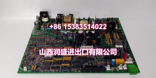
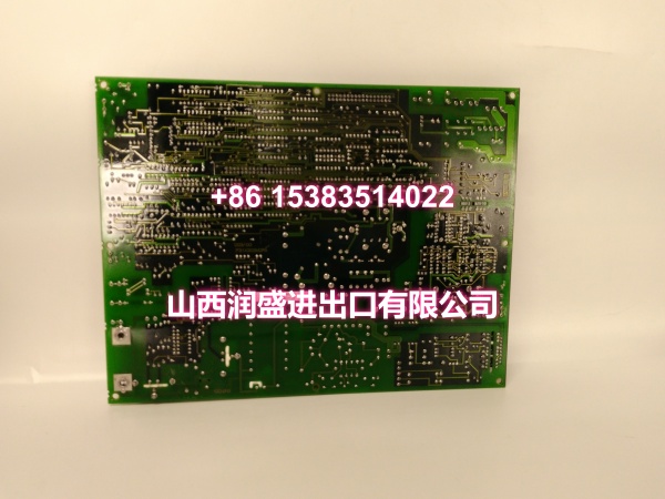
- Connectors: Multiple plug-in connectors along board edges for backplane and cable interfacing
- Mounting: DIN-rail or surface-mount within Mark VI I/O pack chassis
- Configuration Software: ToolboxST (Mark VIe ecosystem compatibility varies by configuration)
Product Introduction (No Fluff)
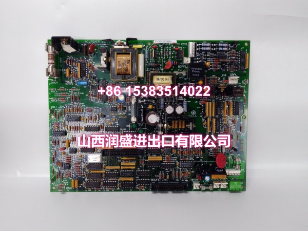
The GE 531X303MCPBBG1 is a processor node board used in GE Speedtronic Mark VI turbine control systems. Associated with assembly number F31X303MCPA00200, this board serves as a key processing and communication element within the Mark VI distributed control architecture.
The Mark VI platform is GE’s integrated turbine control system for gas and steam turbines in generator and mechanical-drive applications. The MCP processor node receives input data from field I/O modules, executes control logic, and communicates across proprietary and industry-standard networks to coordinate turbine protection, sequencing, and monitoring.
This board is typically found in Mark VI I/O packs where distributed processing is required near the turbine skid. It supports redundant network wiring and interfaces with both analog (4–20 mA) and discrete digital signals, making it suitable for critical turbine control loops where uptime and reliability are paramount.
QA & Testing SOP (Dynamic & Transparent)
Processor node boards are mission-critical in turbine control. Each surplus unit undergoes:
- Part Number & Assembly Verification: Confirm the board label reads 531X303MCPBBG1 and verify the associated F31X303MCPA00200 assembly marking.
- Visual Inspection: Check for burnt components, cracked solder joints, corrosion, damaged connectors, and blown fuses. Inspect all edge connectors and plug-in headers.
- Connector Integrity Check: Verify all plug-in connectors along the board edges are secure and free of bent pins or oxidation.
- Power-Up Test: Apply appropriate control power in a test chassis. Confirm the board boots without fault LEDs or watchdog errors.
- Communication Verification: Test network port connectivity. Confirm the processor node establishes communication on the expected network protocol.
- Packaging: Pack in anti-static bags with foam cushioning and rigid outer packaging to protect connectors during transit.
Installation Pitfalls & Guide (Engineer to Engineer)
Always verify the exact part number before swapping. The 531X303MCP family has multiple suffix variants (e.g., MCPBBG1, MCPBDG1, MCPARG1). Suffix differences can indicate hardware revisions or firmware variations that may not be directly interchangeable.
Check associated assembly number F31X303MCPA00200. This ensures the board matches the expected configuration within your Mark VI I/O pack.
Handle edge connectors with care. The plug-in connectors along the board edges are susceptible to damage during removal and insertion. Use proper extraction tools and avoid forcing the board.
Verify network topology before commissioning. The Mark VI system supports redundant network wiring. Ensure the new board is connected to the correct network segment and that redundancy paths are properly configured.
Back up configuration before replacement. If the system is running ToolboxST or a Mark VI configuration tool, export the current application and I/O map before swapping boards.
Replacement Steps:
- Pre-install: Confirm part number 531X303MCPBBG1, back up the current configuration, and prepare LOTO procedures.
- Removal: Power down the I/O pack if possible. Disconnect network and I/O cables. Release the board from its mounting and slide it out carefully.
- Install: Seat the new board firmly into the chassis. Reconnect all network and I/O cables. Verify the board is properly latched.
- Commissioning: Apply power. Verify the processor node boots, establishes network communication, and synchronizes with the controller. Download configuration if required.
Technical FAQ
1. What system is the 531X303MCPBBG1 used in? It is a processor node board for the GE Speedtronic Mark VI turbine control system, used in gas and steam turbine applications for power generation and mechanical drive.
2. What does “MCP” stand for? MCP refers to the processor node / operator interface function within the Mark VI architecture. The board handles processing, network communication, and I/O coordination.
3. Is this board compatible with Mark VIe systems? The Mark VI and Mark VIe are related but distinct platforms. While they share some hardware families, compatibility depends on the specific I/O pack and firmware configuration. Verify against your system documentation or GE support before cross-platform substitution.
4. Can I replace a 531X303MCPBDG1 with a 531X303MCPBBG1? Not without verification. The suffix letters indicate hardware or firmware revisions. While they belong to the same family, interchangeability must be confirmed against the system manual or GE technical support.
5. What warranty do you offer on surplus stock? Terms vary by condition and availability. For surplus industrial control boards, we typically provide a short functional guarantee. Confirm details at time of order.