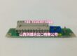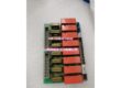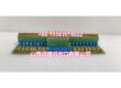
Product Core Brief
- Model: IS200AEADH4ADA
- Brand: General Electric (GE)
- Series: Mark VI (Drive Control)
- Core Function: AEAD (Input Terminal Board) — provides 12 relay input channels with hardware and software filtering for gas/steam turbine drive control systems, enabling direct connection of turbine sensors and actuators without additional instrumentation.
- Product Type: Input Terminal Board (I/O Interface)
- Key Specs: 12 relay channels | Hardware filters (J3: 500 rad/s single-pole; J4: 72/500 rad/s dual-pole) | Software filters (configurable 0/0.75/1.5/3/6/12 Hz) | 30-65°C operating range | Direct sensor/actuator connection
- Condition: New Original / New Surplus
Product Introduction
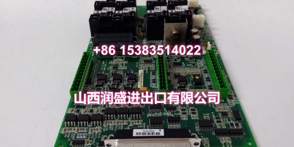
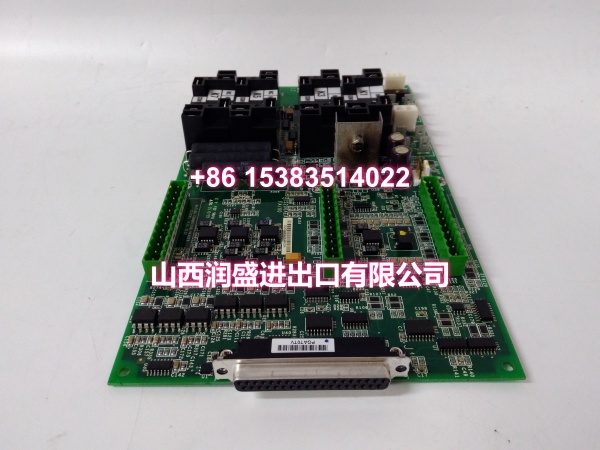
The GE IS200AEADH4ADA is an AEAD (Input Terminal Board) in GE’s Mark VI Drive Control system, designed as the critical interface between field sensors/actuators and the turbine controller. It eliminates the need for intermediate instrumentation by providing direct I/O connectivity, simplifying system architecture and reducing potential reliability and maintenance issues associated with additional signal conditioning hardware.
The board provides 12 relay input channels, organized into two groups of 10 and 2 circuits respectively, each equipped with dedicated hardware filtering to suppress high-frequency noise and interference from the industrial environment. The first group (J3 connector, 10 circuits) features a single-pole roll-off hardware filter with a 500 rad/s cutoff frequency, attenuating high-frequency noise on those input signals. The second group (J4 connector, 10 circuits) is equipped with a dual-pole roll-off hardware filter with cutoffs at 72 and 500 rad/s, providing stronger noise suppression across a wider frequency spectrum. In addition to hardware filtering, the system supports configurable software filtering — a dual-pole low-pass filter with selectable cutoff frequencies of 0, 0.75, 1.5, 3, 6, and 12 Hz — allowing users to tailor the noise rejection characteristics to specific signal types and application requirements.
The IS200AEADH4ADA is designed for installation inside the control cabinet, which should be located in an environmentally controlled room or control room for optimal performance and service life. The board connects directly to turbine sensors and actuators via screw terminals, routing conditioned signals to the Mark VI controller for real-time monitoring and protection logic.
In turbine drive control applications, the AEAD terminal board is commonly used for:
- Reading turbine speed sensor signals (magnetic pickups, proximity probes)
- Monitoring valve position feedback from limit switches and LVDTs
- Reading pressure switch and temperature switch status for safety interlocks
- Monitoring lube oil pressure switch and bearing temperature switch inputs
- Reading flame detector status signals in combustion monitoring
- Monitoring auxiliary equipment status (cooling fans, heaters, lube oil pumps)
- Reading overspeed detection switch inputs for turbine protection
The board is rated for operation in ambient temperatures from 30°C to 65°C and is designed for mounting inside a control cabinet with convection cooling. The cabinet features lockable door handles for security, removable access panels for cable entry from top or bottom, and sealed conduit entries to prevent dust, debris, and moisture ingress.
Key Technical Specifications
| Parameter | Value |
|---|---|
| Manufacturer | General Electric (GE) |
| Product Type | AEAD Input Terminal Board |
| Series | Mark VI (Drive Control) |
| Relay Channels | 12 |
| Hardware Filter (J3) | Single-pole roll-off, 500 rad/s cutoff (first 10 circuits) |
| Hardware Filter (J4) | Dual-pole roll-off, 72/500 rad/s cutoff (second 10 circuits) |
| Software Filter | Dual-pole low-pass, configurable: 0, 0.75, 1.5, 3, 6, 12 Hz |
| Operating Temperature | 30°C to 65°C |
| Dimensions | 17.8 cm (W) x 33.02 cm (H) |
| Installation | Control cabinet (convection cooled) |
| Application | Turbine sensor/actuator interface, discrete input monitoring, safety interlock input |
| Origin | USA |
Quality Control Process
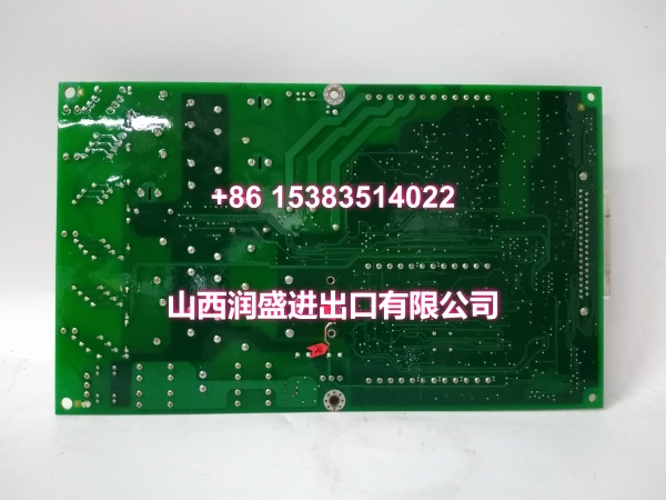
Every IS200AEADH4ADA goes through a full functional bench test before it ships. We start with a visual PCB inspection — checking for cold solder joints, burnt traces, swollen capacitors, and verifying the integrity of all terminal blocks, relay sockets, and connector interfaces. We also inspect the board for any signs of corrosion or physical damage that could compromise long-term reliability.
Then we power it up and verify the relay operation on all 12 channels — actuating each relay and confirming proper switching with a multimeter. We test the hardware filtering on both J3 and J4 connector groups by injecting known frequency signals and measuring the attenuation at the output, confirming the single-pole (500 rad/s) and dual-pole (72/500 rad/s) filter characteristics match specification.
We test the software filter configuration by programming each cutoff frequency (0, 0.75, 1.5, 3, 6, 12 Hz) and verifying the filter response. We verify the input signal integrity by applying known voltage levels to each channel and confirming the board correctly passes the signals to the controller interface. We run a stability test by continuously cycling all 12 relay channels for several hundred cycles, monitoring for contact bounce, timing jitter, or relay failures. We also verify the isolation between channels by measuring resistance between adjacent input channels and between inputs and board ground. Finally, we confirm the board dimensions and mounting hole alignment match the Mark VI cabinet specifications. Each unit ships in anti-static foam with a moisture barrier bag.
Replacement Pitfall Guide
❗ Verify the filter configuration matches your application. The IS200AEADH4ADA has two different hardware filter configurations — J3 (single-pole, 500 rad/s) and J4 (dual-pole, 72/500 rad/s). If your original board had specific channels assigned to J3 or J4 based on the noise characteristics of the connected sensors, the replacement must match this assignment. Connecting a sensor that requires strong noise suppression (dual-pole filter) to a J3 channel (single-pole filter) could result in noisy or unreliable readings. Always verify the channel-to-connector mapping matches your original configuration.
❗ Confirm the software filter settings. The AEAD board supports configurable software filtering with six cutoff frequency options. If the replacement board’s software filter settings don’t match the original, the controller may receive signals with different noise characteristics, potentially causing false trips or missed detections. After installing the replacement, verify the software filter configuration in the Mark VI control software matches your application’s settings.
❗ Don’t skip the relay functional test. After installing the replacement, test each of the 12 relay channels by actuating the connected field device and confirming the relay switches correctly. A relay that sticks or fails to switch can prevent critical safety signals from being read — particularly for functions like turbine trip or overspeed protection.
❗ Verify the cabinet environmental conditions. The board is rated for 30°C to 65°C operation. If the control cabinet’s convection cooling system is compromised (blocked air vents, failed fans, excessive ambient temperature), the board may overheat and fail prematurely. Before installation, verify the cabinet temperature is within the specified range and the cooling system is functioning properly.
❗ Check the cable entry sealing. The control cabinet’s conduit entries must be properly sealed to prevent dust, debris, and moisture from entering the cabinet. Unsealed entries can allow contaminants to reach the terminal board, causing corrosion, short circuits, or relay contact failures. Verify all conduit entries are sealed and the removable access panels are properly installed.
❗ Verify the grounding and shielding. The AEAD board’s input channels are sensitive to electrical noise. Ensure all sensor cables are properly shielded and the shields are grounded at the cabinet entry point. Poor grounding can allow noise to couple into the input signals, defeating the purpose of the hardware and software filters.
Keep these in mind and you’ll cut 90% of rework time.
Compatibility Matrix & Benchmarks
| Original Model | Replacement / Successor Model | Compatibility Level | Migration Notes |
|---|---|---|---|
| IS200AEADH4ADB | Direct | Later revision; verify filter configuration match | |
| IS200AEADH4ADC | Direct | Later revision; drop-in compatible | |
| IS210AEADH4ADA | Direct | IS210 series variant; verify cabinet compatibility | |
| IS200AEADH4A | Functional Equivalent | Earlier revision; verify relay channel count and filter specs |
- Relay Channels: 12 discrete input channels with hardware filtering
- Hardware Filters: J3 single-pole (500 rad/s), J4 dual-pole (72/500 rad/s)
- Software Filters: Configurable dual-pole low-pass (0/0.75/1.5/3/6/12 Hz)
- Operating Range: 30°C to 65°C, convection-cooled control cabinet