Product Quick-Glance Brief
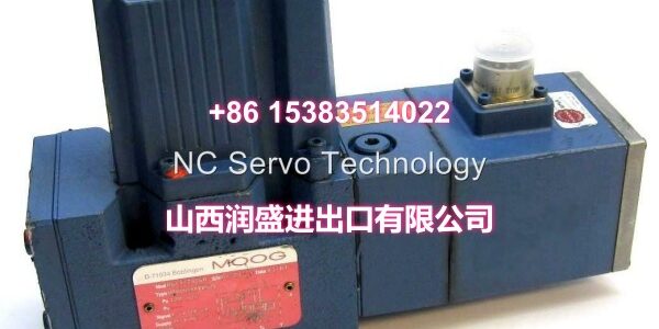
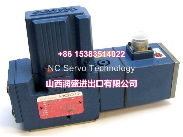
- Model: MOOG -431D-4
- OEM: MOOG
- Category: Servo Valve / Proportional Valve
- Core Function: Provides precise hydraulic flow control for industrial servo applications with integrated electronics.
- Key Specs: D661 Series, -431D-4 Config, 350 bar Max
Technical Overview & Field Application
Precision hydraulic control demands valves that respond instantly to command signals. The MOOG delivers this performance with integrated electronics that simplify your control architecture. No external amplifiers needed. Just clean ±10 V or 4-20 mA signals directly to the valve.
This unit belongs to the versatile D661 family, engineered for high dynamic response in demanding applications. The “-431D-4” suffix defines its specific flow rating, spool type, and electrical interface. Getting this exact match matters. A wrong suffix means incorrect flow capacity or incompatible control signals, leading to tuning nightmares or system damage.
Field engineers trust its integrated LVDT feedback for closed-loop accuracy. The valve continuously monitors spool position and corrects for pressure changes or contamination buildup. This self-correcting behavior maintains tight tolerances in metal forming, test rigs, and plastic injection molding, even as oil conditions degrade over time.
Essential Specifications
| Parameter | Specification |
|---|---|
| Product Series | |
| Configuration Code | -431D-4 |
| Max Operating Pressure | 350 bar (P, A, B Ports) |
| Valve Type | Servo / Proportional |
| Control Signal | ±10 V / ±10 mA / 4-20 mA |
| Feedback | Integrated LVDT |
| Mounting | ISO 4401 (Size Dependent) |
| Operating Temp | -20°C to +80°C (Oil) |
| Cleanliness | ISO 4406 <18/16/13 Recommended |
| Seal Material | FPM (Viton) Standard |
Quality Assurance Protocol
Every MOOG undergoes rigorous validation before shipping. We verify performance, not just functionality.
- Flow Curve Mapping: We sweep the command signal across the full range to confirm linearity and verify the “-431D” flow rating matches OEM specs.
- LVDT Linearity Check: Spool position feedback is validated at multiple stroke points. Non-linearity >1% triggers rejection.
- Dynamic Response Test: Step inputs verify rise time and settling behavior. Sluggish response indicates coil degradation or spool drag.
- Leakage Verification: Internal bypass is measured at rated pressure. Excessive leakage points to spool wear or seal damage.
Note: Units showing hysteresis >2% during testing are quarantined. In servo applications, hysteresis causes positioning errors that compound over cycle time.
Engineer’s Installation / Replacement Notes
Verify the “-431D-4” suffix matches your old valve exactly. The “D” indicates a specific spool type and flow characteristic. Substituting a different letter can lead to poor tuning or unstable control loops.
- Check Connector Pinout: The D661 uses a multi-pin connector. Pin 1 is typically +24V, Pin 2 is 0V, but signal pins vary by revision. Reverse polarity fries the integrated electronics instantly.
- Grounding the Shield: The LVDT signal is low-level. If your cable shield isn’t grounded at the controller end only, you’ll induce noise that looks like spool oscillation.
- Oil Cleanliness Matters: While tolerant, don’t abuse it. ISO 4406 <18/16/13 is the sweet spot. Cleaner oil extends seal life, but don’t over-filter to the point of cavitation.
- Zero Adjustment: If you see drift at null, use the electronic zero trim via the controller, not mechanical stops. Mechanical adjustment on integrated valves is a last resort and often voids calibration.
- Warm-Up Cycle: After installation, run the system at low pressure for 10-15 minutes. This allows seals to seat and oil to reach operating temperature before applying full load.