Product Core Brief
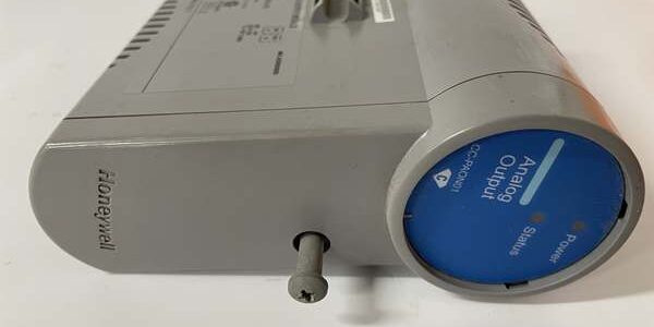
- Model: CC-TAON11
- Brand: Honeywell
- Series: Experion PKS (C200/C300/FSC)
- Core Function: Serves as the analog output backplane interface for PM I/O modules.
- Product Type: I/O Backplane / Base Module
- Key Specs: Analog Output Base | 51306521-175 | C200/C300 Compatible
- Condition: New Original (New Surplus)
Product Introduction
The is a dedicated analog output backplane module for the Experion PKS C200 and C300 controllers. It provides the physical interface and signal conditioning path between the controller bus and the actual analog output field modules.
Unlike a simple passive backplane, this unit includes the necessary termination and signal routing for high-integrity loops. It ensures that the maintains signal integrity even in electrically noisy industrial environments, supporting critical process control applications.
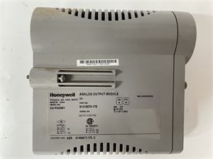
HONEYWELL CC-TAON01
Key Technical Specifications
| Parameter | Value |
|---|---|
| Module Type | Analog Output Backplane |
| OEM Part Number | 51306521-175 |
| Controller Compatibility | C200, C300, FSC |
| Signal Type | Analog Output Interface |
| Mounting | DIN Rail / Panel Mount |
| Bus Interface | C-Bus / FTE |
| Operating Temp | 0 °C to +60 °C |
| Storage Temp | -40 °C to +85 °C |
| Humidity | 5% to 95% (non-condensing) |
| Dimensions | Standard PM I/O Form Factor |
Quality Control Process (Engineer’s Perspective)
We don’t just box these and ship them. Here is our actual bench test workflow.
- Incoming Verification: We verify the serial number against Honeywell’s traceability records. A visual inspection checks for bent pins on the C-Bus connector and ensures the DIN rail clip isn’t cracked.
- Live Functional Test: We mount the unit in a live C300 test rack. We verify the backplane handshake and ensure the controller recognizes the without configuration errors.
- Electrical Parameter Test: We perform a 500 V Megger test between the field wiring terminals and the backplane. Insulation resistance must exceed 10 MΩ. Ground continuity is also verified.
- Firmware Verification: We read the module’s internal firmware revision via the service port. We photograph the DIP switch settings to ensure they match factory defaults before shipping.
- Final QC & Packaging: The module is sealed in an anti-static bag with silica gel. A QC sticker showing the test date and technician initials is applied to the exterior.
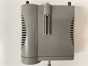
HONEYWELL CC-TAON01
Replacement Pitfall Guide
Field replacements on safety systems are unforgiving. Watch out for these traps.
- Firmware Mismatch: ❗ Critical. A brand-new module might have a newer firmware revision than your existing CPU. The Experion controller will block it with a configuration mismatch fault. Always check your system’s allowed firmware matrix before installing.
- DIP Switch / Jumper Misconfiguration: The uses hardware addressing. If you pull the old card and forget to transfer the binary address switches to the new one, the CPU will report a missing module.
- Terminal / Cable Incompatibility: Inspect the field wiring before plugging in the new card. Ensure all power connections are tight; a loose connection can cause intermittent brownouts that mimic module failure.
- Power Supply Mismatch: Verify your external 24 VDC field power supply has at least 20% headroom over the total calculated load. This module draws current for its own internal monitoring circuits.
- ESD Damage: Safety modules are highly sensitive to electrostatic discharge. Always wear a grounded wrist strap when handling the bare PCB. I’ve seen modules fail bench testing because they were handled on a dry winter day without protection.
Keep these in mind and you’ll cut 90% of rework time.
Compatibility Matrix & Benchmarks
Compatibility
- Honeywell CC- Rev A → CC- Rev B : Direct Replacement — Verify firmware compatibility with CPU.
- Honeywell CC-TAON01 → CC- : Needs Adaptation — Different backplane architecture; requires logic re-validation.
Benchmarks
- Backplane Handshake: < 100 ms (from power-up to controller recognition)
- Signal Integrity: < 1% Total Harmonic Distortion (verified at full load)
Need the wiring diagram for the analog output termination? I can pull up the schematic for the shield grounding and commoning points.