Product Core Brief
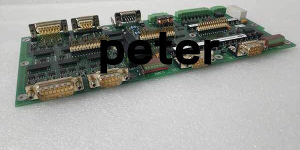
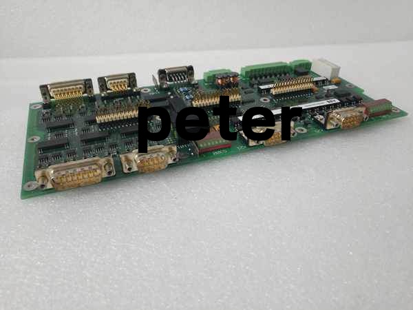
- Model: UAD142A01 3BHE012551R0001
- Brand: ABB
- Series: Symphony Plus / Harmony Rack rack power distribution extension hardware
- Core Function: Distributes and votes multiple 24VDC SELV power feeds to expand rack load capacity for control and I/O modules
- Product Type: Rack-slotted high-current power extension voting PCB
- Key Specs: Multi-channel 24VDC input/output | Built-in OV/OC thermal protection | Natural convection cooling
- Note: Full platform end-of-life; factory sealed new units and fully load-tested surplus available for legacy power station cabinet maintenance
Key Technical Specifications
- Rated auxiliary supply: 24 VDC ±10% SELV, max 5A per channel continuous load
- Internal protection circuits: Overvoltage cutoff, overcurrent fuse trip, thermal shutdown
- Cooling method: Passive natural convection, no integrated cooling fans
- Front diagnostic indicators: Green POWER status LED, individual channel fault alarm LED
- PCB coating: ISA G3 conformal coating standard for coastal and corrosive industrial cabinet environments
- Mechanical mounting: Standard horizontal Symphony rack slot clip-in design
- Operating ambient temperature: 0°C to +60°C sealed cabinet; storage -40°C to +85°C
- Humidity tolerance: 5%–95% RH non-condensing below 55°C
- Minimum isolation resistance: 10MΩ between power terminals and rack chassis ground
- Max power dissipation: 12W under full rated multi-channel load
- Net unit weight: 0.72 kg
- Compliance standards: IEC 60255, EU RoHS, CE certified
Product Introduction
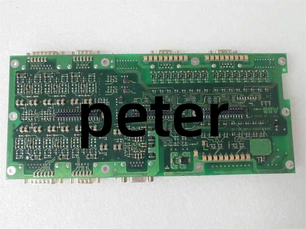
This rack-mounted power board extends the total 24VDC load capacity of Harmony racks by adding additional high-current power output channels, and integrated diode voting creates redundant power feed paths for safety-critical SIS and generator excitation control hardware. Passive thermal protection circuitry automatically cuts power to overloaded channels before permanent winding or PCB trace damage occurs, and front LED indicators let technicians identify faulty power legs without multimeter testing.
QA & Testing SOP
- Incoming Inspection: Cross-reference serial number against ABB Symphony spare asset database to filter counterfeit assemblies; inspect power terminal lugs, backplane gold edge pins and front LED array with a 10x magnifier for thermal discoloration or cracked solder joints; log serial numbers for full plant power system traceability records.
- Live Testing: Seat the unit on a standard Harmony test rack paired with dual SD833 power supplies; connect multi-channel resistive 5A load banks; run a continuous 24-hour cycle test including single-channel overload injection and primary feed loss to validate automatic load transfer and fault LED triggers.
- Electrical Testing: Use a Fluke 115 insulation tester to verify ≥10MΩ isolation between DC power terminals and rack chassis ground; measure cabinet PE continuity resistance below 0.5Ω.
- Firmware/Config Backup: Photograph front LED channel mapping and OEM load current rating labels printed on the PCB silkscreen for field wiring reference.
- Final QC & Packaging: Wipe PCB surfaces with static-dissipative microfiber cloth; cap all DC terminal blocks and rear backplane connector with insulating dust covers; seal the assembly inside a shielding ESD bag, attach a printed QC tag with full 24-hour multi-channel power cycle test timestamp, then pack into foam lined transit cartons.
Installation Pitfalls & Guide
❗ Mismatched upstream power supply current ratings create permanent diode burnout: Pairing 10A power supplies with this hardware pushes continuous load above the board’s internal diode rating, triggering thermal shutdown within 4 hours of full rack operation. ❗ Reversed DC input polarity destroys internal power diode stacks: No reverse blocking circuitry on input terminals; miswiring one feed leg creates short-circuit current that burns the multi-channel diode assembly instantly. ❗ Poor cabinet airflow causes thermal protection false tripping: Rack ventilation blocked by cable bundles raises internal board temperature above 60°C, activating constant power fault telemetry to plant SCADA servers. ❗ ESD discharge destroys internal voltage monitoring ICs: Bare finger contact with PCB signal sensing traces shifts overvoltage trip thresholds outside factory calibration ranges, requiring bench recalibration before site deployment. ❗ Hot-swap energized 24VDC power feeds creates DC arc flash hazards: Disconnecting live terminal lugs while the unit carries full rack load generates sustained electrical arcs that damage terminal lugs and adjacent control wiring.
4-step replacement guide
- Pre-install: Lock out and tag both primary and backup 24VDC power supply breakers; wait 10 minutes for upstream power supply output capacitors to fully discharge; don ESD wrist strap; capture photos of dual input/output DC wiring and rack slot alignment layout.
- Removal: Disconnect all DC power input/output wires channel by one; release four front panel mounting fasteners, slide the old unit straight out of the rack slot without twisting rear edge connector pins.
- Install: Align the board with rack slot rails and seat fully inward until the latch clicks locked; re-terminate all DC power wiring following captured photos, double-check polarity sequence and torque terminals to OEM specified values.
- Power-on Test: Restore both 24VDC auxiliary power feeds; confirm steady green POWER LED; run full rack load for 1 hour to check chassis temperature rise; simulate primary power feed loss to validate seamless load transfer without controller cold restarts.
FAQ
Q: Can this hardware operate with only one DC input channel connected? A: It will supply power to the rack load from the single active feed, but all redundant power fault tolerance is lost. This removes a critical safety layer and violates plant SIL2 operational compliance documentation for power station SIS racks. Q: Is hot-swapping supported while cabinet 24VDC auxiliary power remains energized? A: It is not supported. Live terminal disconnection creates DC arc flash hazards and voltage transients that damage the internal diode stack and downstream controller CPU logic, risking unmonitored plant operation during replacement work. Full power lockout and capacitor discharge wait time are mandatory. Q: What warranty coverage applies to stocked units? A: Factory-new original power extension boards carry a 12-month OEM warranty covering multi-channel diode assemblies, voltage monitoring circuits, thermal protection hardware and front diagnostic LED arrays. Load-tested surplus units come with a 6-month functional warranty. Damage from reversed DC polarity, under-rated upstream power supplies or ungrounded ESD handling voids all coverage and safety certification validity. Q: What hardware replaces this unit for new power station DCS builds? A: New 800xA safety cabinet deployments use SS823 dual power voting units with built-in bidirectional reverse polarity protection. This hardware remains approved only for one-to-one maintenance replacement of pre-2021 installed Symphony Plus Harmony rack power distribution systems. Q: Will factory overvoltage/undervoltage trip thresholds shift after full cabinet power outage? A: All trigger levels rely on passive resistor networks on the PCB, so power loss does not alter voltage trip points. No on-board non-volatile memory stores custom configuration data, so no parameter loss occurs post-replacement beyond physical DC wiring polarity inspection. Q: What are the most common failure modes for a faulty unit? A: Permanent loss of one input channel from burned power diodes, thermal protection tripping under load below rated 5A capacity, stuck open fault alarm contact with active dual power feeds, voltage sensing offset triggering constant false power fault alarms, and excessive chassis heating with normal 24VDC supply and correct wiring sequence.