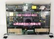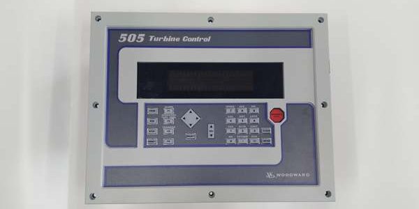
Product Core Brief
- Model: 9907-028
- Brand: WOODWARD
- Series: SPM-A Speed & Phase Matching generator synchronizer family
- Core Function: Automatically align generator frequency and phase with utility bus, send raise/lower bias signals to prime mover governors to enable bumpless breaker closure; no built-in voltage matching capability.
- Product Type: Back-panel mount standalone genset synchronizer interface module
- Key Specs: 50/60 Hz dual frequency support | ±10° adjustable phase window | No voltage matching logic | Relay breaker close output ⚠️ EOL — limited surplus stock remaining
Product Introduction
The WOODWARD 9907-028 acts as a dedicated parallel interface between generator bus voltage sensing circuits and Woodward digital speed governors like the 8290-194. It only corrects frequency and phase, requiring external voltage regulation hardware to balance generator and grid voltage before sync enable.This unit differs from the 9907-029 sibling model by omitting integrated voltage trim logic, cutting component count for sites with separate automatic voltage regulators. OEM field logging records a 54,000 hour MTBF under steady 50 °C generator control cabinet runtime.
Key Technical Specifications
| Parameter | Value |
|---|---|
| Supported Grid Frequencies | 50 Hz, 60 Hz user selectable via internal jumper |
| AC Bus Input Voltage | 115 VAC / 230 VAC dual range, ±10% input tolerance |
| Phase Matching Window | Adjustable -10° to +10° phase angle offset for breaker close permission |
| Operating Modes | OFF, RUN, CHECK, PERMISSIVE; selected via external dry contact switch |
| Governor Bias Output | Analog raise/lower speed trim signal compatible with Woodward 2301, 723PLUS, 8290 series governors |
| Breaker Control Output | Isolated Form-C relay contact for breaker close interlock signal |
| Maximum Power Consumption | 5 W full operating load |
| Operating Supply Range | 18 VDC to 32 VDC (24 VDC nominal cabinet auxiliary feed) |
| Mechanical Mount Format | Standard back-panel chassis mount, NEMA Type 1 equivalent enclosure |
| Net Unit Weight | 1.75 kg |
| Continuous Operating Ambient Temp | -40 °C to +70 °C full rated sync performance; linear derate above 60 °C |
| Storage Temperature Range | -40 °C to +85 °C, 5–95 % RH non-condensing |
| Onboard Diagnostics | Loss of generator bus voltage alarm, loss of utility bus voltage fault flag |
| Integrated Protection Circuits | AC input surge clamping, reverse DC supply polarity lockout, relay coil transient suppression diodes |
| Certifications | UL, CE, EN61000 Class A industrial EMC filtering for power generation facilities |
Quality Control Process (Engineer’s Perspective)
- Incoming Verification: Cross-reference serial numbers against Woodward OEM trace databases; inspect rear terminal block screw threads for stripping, PCB bus sensing solder joints for microcracks, relay contact surfaces for pitting. Photograph rear I/O pinout for generator control cabinet wiring reference.
- Live Functional Test: Mount the unit to a DIN test panel paired with dual programmable AC voltage sources simulating generator and utility bus; run a continuous 24-hour auto-sync cycle test across both 50 Hz and 60 Hz frequency configurations. Log DC supply voltage stability with a Fluke 115 digital multimeter for the full test duration.
- Electrical Parameter Test: Perform a 1000 V Megger insulation resistance test between AC bus input circuits and module chassis ground; pass threshold set at >10 MΩ. Verify breaker close relay only energizes when phase and frequency fall within the configured ±10° window.
- Jumper & Mode Verification: Record factory default frequency jumper position and phase window offset setting; document external mode switch wiring logic for customer genset site commissioning reference.
- Final QC & Packaging: Wipe rear terminal block contact surfaces to remove oxidation; seal the unit inside an anti-static foam bag, affix a dated QC Pass label listing all completed sync timing and insulation test metrics before rigid shock-resistant carton packing.
Replacement Pitfall Guide
❗ Model Revision Mismatch Risk: Older SPM-A synchronizer firmware pre-Rev F lack extended phase window adjustment registers. Installing the unit generates unplanned breaker close interlock blocks during narrow grid frequency transients. Cross-check site governor software release notes before swap-out.❗ Bus Wiring Shield Ground Misconfiguration Risk: Unshielded AC voltage sensing wiring run parallel to high-current generator excitation cabling injects EMI noise that distorts phase angle detection and delays sync permission signals. Use factory twisted-pair shielded AC sensing assemblies, terminate shield ground at only the main control cabinet terminal block end.❗ Panel Mount Partial Seating Risk: Misaligned back-panel mounting creates loose rear terminal contact points that drop generator or utility bus voltage signals during generator startup ramps. Secure all four mounting fasteners to lock the module flush against the cabinet backplate surface.❗ Generator Cabinet Power Headroom Miscalculation Risk: A cabinet with three of these synchronizer modules draws 0.63 A total from the VM310 24 V auxiliary supply. Calculate total load with a mandatory 20% power margin to avoid voltage sag during continuous sync cycle polling.❗ Uncontrolled ESD Damage Risk: Dry generator control room air creates static charge buildup. Touch a grounded anti-static mat for three full seconds before handling rear AC and DC terminal blocks; ungrounded contact destroys low-tolerance bus phase sensing ASICs.Keep these in mind and you’ll cut 90% of rework time.
Compatibility Matrix & Benchmarks
Compatibility Matrix
- 9907-029 voltage-matching SPM-A synchronizer → 9907-028 : Needs Adaptation — site must install external AVR voltage trim hardware to replace lost internal voltage matching functions
- WOODWARD 8290-194 digital speed governor → 9907-028 : Direct — synchronizer analog bias output feeds governor speed trim input for frequency correction
- VM310 24 V cabinet auxiliary power supply → 9907-028 : Direct — regulated 24 V output falls within the unit’s 18–32 V operating window without extra voltage conditioning
- 5453-279 MicroNet TMR turbine control chassis → 9907-028 : Needs Adaptation — add Modbus RTU-to-Ethernet gateway hardware to bridge synchronizer discrete fault contacts to TMR RTN backbone
- CML40.2-SP-330-NA-NNNN-NW Rexroth SERCOS motion PLC → 9907-028 : Needs Adaptation — wire module bus-loss and sync-ready dry fault contacts to PLC digital inputs, map phase offset status via discrete input polling