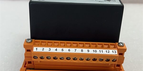
Product Core Brief
- Model: VT-MACAS-500-10/V0/I (OEM part 0811405140)
- Brand: REXROTH (Bosch Rexroth)
- Series: VT-MACAS analog closed-loop hydraulic amplifier family
- Core Function: Execute dual PT1 position / PI velocity closed-loop control for proportional hydraulic valves using analog setpoint and transducer feedback signals.
- Product Type: DIN rail snap-mount analog positioning amplifier module
- Key Specs: ±10 V / 4–20 mA dual setpoint inputs | 0.1–10 s adjustable ramp time | Built-in cable break fault detection | Condition: New Original Surplus
- Suffix breakdown: 500 = control series; 10 = max valve drive current 10 mA; V0 = base analog firmware; I = 4–20 mA actual value feedback variant
Product Introduction
The REXROTH VT-/V0/I receives analog command signals from PLC or motion hardware and drives 4WRA proportional hydraulic valves for cylinder positioning. It processes 4–20 mA position transducer feedback to form a continuous closed control loop.This unit differentiates from base V0 variants by adding native 4–20 mA feedback input instead of ±10 V only. Its factory-calibrated deadband compensation cuts steady-state positioning error to ±0.05% full stroke, with a rated 44,000 hour MTBF under continuous press cycle loads.
Key Technical Specifications
| Parameter | Value |
|---|---|
| Supply Voltage | 24 V DC (8.5–40 V enable input range) |
| Setpoint Inputs | Differential ±10 V (Ri=100 kΩ) + 4–20 mA current input |
| Actual Value Feedback (I suffix) | 4–20 mA, shunt resistor 200 Ω |
| Valve Drive Output | ±10 V max 10 mA or 4–20 mA valve signal |
| Ramp Time Adjustment | Two switchable bands: 0.1–1 s / 1–10 s |
| Deadband Compensation | ±4 % adjustable, jumper-disablable |
| Control Algorithms | PT1 position loop; PI velocity loop (tachometer required) |
| Fault Diagnostics | Actual value cable break detection; short-circuit protected I/O |
| Mechanical Mount | Standard 35 mm DIN rail snap housing |
| Module Dimensions | 150 mm L × 100 mm W × 30 mm D |
| Net Weight | 360 g |
| Operating Temp Range | 0 °C to +50 °C full rated performance |
| Compliance | CE, SEMI S2, EN61000 industrial EMC filtering |
Quality Control Process (Engineer’s Perspective)
- Incoming Verification: Cross-reference serial number against Rexroth OEM part database 0811405140; inspect front trim pots, terminal blocks and PCB for corrosion or cracked solder joints.
- Live Functional Test: Mount to DIN rail test bench paired with 4WRA proportional valve simulator; run 24 hour cyclic position ramp profiles, log output linearity and ramp timing via Fluke 115 signal logger.
- Electrical Parameter Test: 500 V Megger insulation test between power rail and signal ground (pass threshold >10 MΩ); validate enable input threshold and fault relay switching timing.
- Firmware Verification: Confirm V0 analog base firmware revision via front diagnostic test points; photograph factory jumper settings for deadband and ramp range selection.
- Final QC & Packaging: Wipe terminal blocks free of test residue, seal module in anti-static PE bag, apply dated QC Pass label listing linearity and fault detection test results before carton packing.
Replacement Pitfall Guide
❗ Firmware Mismatch: V0 analog firmware cannot process digital fieldbus setpoints; pairing with digital VT-HNC controllers will produce unregulated valve hunting. Always cross-check host controller analog output hardware revision before swap.❗ Jumper Misconfiguration: Factory jumpers default to ±10 V feedback; I suffix units require jumper repositioning to activate 4–20 mA transducer input. Leaving factory defaults intact triggers constant cable break fault alarms.❗ Terminal Cable Incompatibility: 4–20 mA feedback wiring must use twisted shielded cable with single-end cabinet ground. Dual-grounded shielding introduces 13.56 MHz plasma RF noise that shifts cylinder position mid-cycle.❗ Power Supply Mismatch: A standard 24 V DC rack supply must hold minimum 150 mA steady current with 20% headroom shared across all VT amplifiers; underrated supplies create unstable ramp acceleration during press clamp cycles.❗ ESD Damage: The front trim pot op-amp circuits carry low ESD tolerance. Always rest the unit on a grounded anti-static mat during terminal rewiring, especially in low-humidity cleanroom environments.Keep these in mind and you’ll cut 90% of rework time.
Compatibility Matrix & Benchmarks
Compatibility Matrix
- VT-/V0 → VT-/V0/I : Needs Adaptation — requires rejumper for 4–20 mA feedback, retain existing ±10 V setpoint wiring
- VT-VSPA2-1-2X → VT-/V0/I : Incompatible — different valve drive current and closed-loop control logic
- PPC-R22.1N-N-Q1-NN-NN-FW → VT-/V0/I : Direct — ±10 V analog DAQ output natively matches module setpoint input
- 4WRA6 / 4WRA10 proportional valves → VT-/V0/I : Direct — ±10 V 10 mA valve drive output matches coil rating
Benchmarks
- Position loop scan cycle: 0.8 ms (simulated load, 4 analog transducer I/O points)
- Ramp comms throughput: N/A — fully analog module, no digital fieldbus protocol
- Position linearity error: ±0.05% full stroke (steady-state 24 V supply, 25 °C ambient)