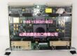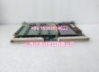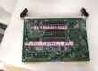
Product Core Brief
- Model: HMV01.1R-W0018-A-07-, OEM part number R911297460
- Brand: Bosch Rexroth Indramat (IndraDrive M modular drive platform)
- Series: regenerative mains feed-in / rectifier unit family
- Core Function: Convert three-phase industrial mains to stabilized 700V DC shared intermediate bus for all connected HDS/HMS servo power stages; regenerate motor braking energy back to factory mains grid to eliminate large external brake resistors, communicate fault/state signals via front diagnostic I/O terminal to PPC-R22 motion CPU
- Product Type: Vertical DIN rail mount regenerative rectifier module; suffix breakdown:
- 1R = Regenerative energy feedback topology
- W0018 = 18kW continuous rated power
- A = Base hardware revision
- 07 = Nominal 700V DC intermediate bus voltage class
- = Standard front-panel fault/status I/O terminal block, no extra fieldbus expansion card, no built-in external brake chopper
- Key Specs: 18kW continuous regenerative power | 3AC 380–480V mains input | Stabilized 700V DC shared bus | Integrated forced air blower cooling | Regenerative grid feedback | 24VDC auxiliary control supply
- Note: OEM discontinued new mass production; limited factory surplus and fully load-calibrated refurbished inventory available. Matches DIAX04 / IndraDrive M HDS02.2 servo drive stacks paired with PPC-R22 RECO rack motion controllers for machine tools and semiconductor substrate handling lines. Cannot substitute non-regenerative .1E passive rectifier variants without cabinet power circuit rework.
Key Technical Specifications
Mains Input & Power Rating
- Three-phase AC input range: 380 VAC ~ 480 VAC, 50 / 60 Hz industrial mains
- Continuous rated regenerative output power: 18 kW
- Continuous DC bus output current: 24 A RMS
- Short-circuit withstand rating: 42,000 A RMS
- Nominal stabilized DC intermediate bus voltage: 700 VDC (operating window 530–750 VDC)
- Auxiliary control logic supply: 24 VDC ±20% unregulated cabinet rail, steady standby power draw 30 W
Thermal & Mechanical
- Cooling: Internal integrated axial blower forced air cooling
- Mount form factor: Standard 35mm vertical DIN rail rack mount
- Total unit weight: 13.5 kg
- Enclosure protection class: IP20 (cabinet-only installation)
- Ambient operating temperature: 0°C ~ +40°C full rated output; linear derate above +40°C up to max +55°C
- Storage / transport temperature: -25°C ~ +70°C, non-condensing humidity 5–95% RH
Electrical Protection Circuits
- Mains overvoltage / undervoltage lockout (OVP / UVP)
- DC bus overvoltage, overcurrent short-circuit shutdown
- Internal over-temperature thermal shutdown with fault flag output
- Reverse polarity protection for DC bus and auxiliary control supply
- Mains contactor interlock, phase loss detection
- Built-in smart energy mode for low standby power consumption
Interface Definition ( suffix)
- F: Front-panel X31 multi-function diagnostic terminal block
- NN: No PROFIBUS / SERCOS expansion communication card populated
- N1: Standard digital fault/status I/O (power ready, regenerate active, overtemp, mains fault relay contacts)
- No integrated external brake chopper; braking energy fully returned to factory mains via regenerative topology
Compliance & Compatibility
- Certifications: CE, UL, EN61000 industrial EMC, SEMI S2 for cleanroom wafer handling equipment
- Compatible power stages: HDS02.2 series SERCOS servo drives, HMS01 single-axis inverters
- Compatible motion CPU: PPC-R22 RECO rack real-time motion controllers, VisualMotion Toolkit commissioning software
Product Introduction
This regenerative feed-in rectifier supplies a stabilized shared 700V DC bus for multi-axis servo systems built on Rexroth DIAX04 / IndraDrive M platforms. Unlike passive E-type rectifiers that waste braking heat via external resistors, the R regenerative topology feeds all deceleration energy back to the facility power grid, cutting cabinet heat buildup and eliminating large brake resistor installation costs.The integrated blower maintains full 18kW power output under continuous vertical axis static load cycles common in wafer transfer and precision press equipment. Front I/O terminals broadcast power unit fault and operational status to the PPC-R22 motion CPU, enabling machine HMI fault diagnostic trending without separate signal wiring. The shared DC bus architecture allows multiple HDS02.2 servo drives to exchange energy between accelerating and decelerating axes internally before grid feedback.
QA & Testing SOP (Transparency Building)
- Incoming Inspection: Cross-reference serial number against Rexroth OEM vital product databases matching part R911297460; visual scan for dented heat sink fins, cracked blower fan blades, swollen DC bus electrolytic capacitors, charred mains terminal lugs, and damaged X31 diagnostic terminal blocks. All mains, DC bus and control wiring pin assignments photographed pre-disassembly.
- Live Bench Testing: Mount unit to DIN rail test rack paired with simulated multi-axis HDS servo load bank; run continuous 24-hour cyclic acceleration/deceleration load profile alternating motoring and regenerative energy feedback cycles. Fluke power analyzer verifies grid regenerative power transfer efficiency and three-phase mains current balance.
- Protection & Signal Validation: Trigger all fault modes (phase loss, overtemp, DC bus overvoltage) to confirm correct relay contact state and fault code reporting via front I/O terminals. Validate 700V DC bus voltage regulation across full 0–18kW load range.
- Power Stage Calibration: Trim mains current loop gain/offset to OEM factory tolerance; test blower startup speed and thermal shutdown trigger thresholds per datasheet specification.
- Final QC & Packaging: Replace degraded DC bus electrolytic capacitors and worn blower fan assemblies during refurbishment cycles; cap unused mains and DC bus terminal ports with OEM insulating dust plugs, wrap unit in static-dissipative foam, affix printed QC tag listing DC bus regulation accuracy, regenerative efficiency and all protection circuit test metrics before sealed wooden crate shipping.
Installation Pitfalls & Guide (Engineer to Engineer)
❗ Non-Regenerative E Variant Mismatch Risk: .1E passive rectifiers lack grid energy feedback. Direct replacement of R regenerative unit with E variant requires installation of high-power external brake resistors and full cabinet mains circuit rework. Photograph original regenerative grid wiring layout before unit removal to avoid excess heat buildup mid-production batches.❗ Blower Airflow Blockage Hazard: Cabinet cable bundles covering front/rear ventilation slots create rapid thermal buildup, triggering unplanned over-temperature shutdown during heavy regenerative deceleration cycles. Maintain minimum 50mm unobstructed airflow clearance around the unit heat sink surfaces.❗ Shared DC Bus Parallel Mismatch Risk: Multiple regenerative units wired in parallel require identical firmware versions and synchronized voltage regulation setpoints. Mismatched parameters create circulating DC bus cross-current that accelerates capacitor aging.❗ Mains Phase Imbalance Overload Hazard: Three-phase mains line current imbalance exceeding 10% triggers phase-loss fault interlock. Verify factory mains transformer output balance before commissioning the power unit.❗ Catastrophic ESD & High-Voltage Hazard Risk: DC bus terminals carry 700V hazardous live voltage; fully bleed DC bus capacitance via dedicated discharge circuit before disassembly. Unshielded control board ASIC circuits sustain permanent leakage damage from ungrounded handling; certified ESD wrist strap and conductive anti-static mat mandatory before touching front X31 terminal blocks or internal PCB components.4-Step Replacement Guide:
- Pre-install: Execute full machine lockout-tagout, cut facility three-phase mains supply, fully discharge shared DC bus energy via safe bleed circuit, export all DC bus monitoring and power unit fault logic parameter sets from PPC-R22 CPU via VisualMotion Toolkit offline PC software.
- Removal: Disconnect three-phase mains power lugs, shared DC bus positive/negative copper busbars, 24VDC auxiliary control wiring and front diagnostic I/O terminal cables one at a time; release DIN rail bottom snap tab, slide power unit vertically free from rack and rest on vibration-dampened ESD foam pad. Record mains phase sequence, DC bus polarity and fault signal pin assignments.
- Install: Snap replacement unit onto standard 35mm DIN rail, ensure unobstructed blower airflow clearance, re-terminate mains lugs, DC bus busbars and control/diagnostic wiring matching photographed layout; separate high-current mains cabling from low-voltage control signal wiring per EMC cabinet wiring rules.
- Power-on Test: Restore cabinet 24VDC auxiliary control supply first, confirm front-panel power ready LED illuminates steady green; then energize three-phase mains, validate stabilized 700V DC bus voltage, run 30-minute cyclic motoring/regenerative load test to confirm consistent grid energy feedback and fault-free status signal reporting to the motion CPU.
FAQ (Frequently Asked Questions)
Q: Can this R regenerative power unit replace E passive rectifier variants on identical multi-axis machine racks without wiring rework?A: No out-of-box cross-compatibility. E-type rectifiers lack grid feedback circuitry and require external brake resistors to dissipate deceleration energy. Swapping R for E requires new high-power resistor cabinet installation and DC bus circuit modification; swapping E for R requires removal of existing brake resistor hardware and mains grid feedback wiring addition. All DC bus monitoring parameters must be reloaded and retuned regardless of variant swap.Q: Does this regenerative feed-in unit support hot-swapping while cabinet three-phase mains and shared DC bus remain energized?A: Mains lugs and DC bus terminals lack staged hot-swap power pin sequencing. Live extraction injects severe high-voltage transients into the shared DC bus, corrupting nvRAM stored axis tuning parameters and risking permanent damage to all connected HDS servo drive power stages. Full mains lockout and complete DC bus bleed-down is mandatory before disconnection.Q: What warranty separates factory surplus stock from fully refurbished units?A: Unopened original Rexroth-certified surplus carries a 12-month industrial warranty covering DC bus voltage regulation drift, regenerative efficiency degradation and blower fan premature wear. Refurbished calibrated units ship with a 6-month limited functional warranty; reused DC bus electrolytic filter capacitors exhibit gradual capacitance loss under continuous cabinet heat and cyclic regenerative load.Q: Will swapping this mains feed-in unit erase stored DC bus monitoring thresholds and regenerative energy logic parameters in the motion CPU?A: All DC bus overvoltage/undervoltage alarm limits and regenerative mode monitoring logic reside in the RECO rack CPU’s onboard Flash and nvRAM memory, independent of the HMV power unit hardware. Export a complete parameter backup via VisualMotion Toolkit before disassembly to avoid full power system logic retuning post-install.Q: Can this hardware operate with legacy VisualMotion Toolkit v4 commissioning software released prior to 2006 without firmware updates?A: The front diagnostic I/O interface requires VisualMotion Toolkit v5 minimum software version; v4 builds lack device description files for regenerative power unit fault register mapping, leading to missing DC bus trending screens and incomplete power system diagnostic visibility on the VEP40 HMI.Q: What expected service window applies to surplus versus refurbished power units in 24/7 high-volume semiconductor production environments?A: Original surplus units target scheduled DC bus capacitor and blower fan replacement at 41,000 operating hours. Refurbished variants degrade at 32,000 hours; aged electrolytic filter capacitors lose capacitance over time, widening DC bus voltage ripple and triggering unstable axis speed hunting during fast wafer transfer deceleration cycles.Q: What functional difference separates and FCN1 front interface suffixes on the same .1R base power unit?A: provides standard digital relay fault/status I/O only with no built-in brake chopper hardware; FCN1 variants integrate an internal brake transistor circuit for low regenerative duty cycle applications that do not require full grid energy feedback, eliminating small external brake resistors but reducing maximum continuous regenerative power rating.