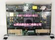
Product Core Brief
- Model: 3500/42M 140734-02 (Front measurement card; matched rear terminal base PN 140471-01)
- Brand: Bently Nevada (Baker Hughes)
- Series: 3500 Machinery Protection TSI Rack System
- Core Function: Four-channel universal monitor that processes both eddy-current proximity probe signals and seismic Velomitor/accelerometer inputs for full-spectrum turbomachinery condition monitoring and safety protection
- Product Type: Single-slot hot-swappable split front/rear base mixed proximity + seismic M-series module
- Key Specs: 4 software-pairable universal channels | Native support for position and vibration transducers | 7.7 W typical power draw
- Condition: New Original factory sealed with standard OEM lead time; fully calibrated refurbished surplus stock ships within 3 working days
Key Technical Specifications
- Channel Architecture: 4 independent inputs, configured in pairs (Ch1/Ch2 as one function set; Ch3/Ch4 as second function set)
- Supported Transducer Families:
- Proximity: 3300 XL eddy-current probes (5/8/11/25 mm range)
- Seismic: Velomitor velocity sensors, piezoelectric accelerometers
- Measurable Parameters: Radial vibration, thrust position, eccentricity, differential expansion, shaft absolute, velocity, acceleration, REBAM, circular acceptance orbit monitoring
- Transducer Excitation: −24 VDC regulated supply for proximity probes
- Frequency Response: 0.5 Hz to 10 kHz for vibration capture; DC range for static shaft displacement
- Analog Recorder Output: Isolated per-channel 4–20 mA proportional scaled signal, max 550 Ω load resistance
- Power Consumption: 7.7 W continuous draw from rack 24 VDC backplane bus
- Galvanic Isolation: 1500 VAC separation between each field input circuit and rack ground bus
- Operating Ambient: −30 °C to +65 °C standard cabinet; conformal coated variant rated −40 °C to +85 °C offshore service
- Physical Dimensions: 241.3 mm H × 24.4 mm W × 241.8 mm D; total assembly weight 0.91 kg
- Compliance Standards: API 670, CE EMC, UL Class I Div 2, ATEX Zone 2 Ex nC IIC T4, SIL 2 functional safety
- Front Panel Indicators: OK (operational status), TX/RX (backplane communication), BYPASS (channel inhibit mode)
Product Introduction
Most gas turbine and large compressor racks require simultaneous monitoring of shaft position via proximity probes and casing vibration via seismic sensors. This unit eliminates the need to deploy separate 3500/40M proximity-only and 3500/44M aeroderivative seismic cards by supporting both transducer types on the same module slot.Its split rear terminal base lets maintenance crews rework field cabling, add intrinsic safety barriers, or repair damaged terminals without extracting the front measurement card during planned outages. This component cannot process RTD or thermocouple thermal signals; dedicated 3500/60 or 3500/61 temperature cards are required for bearing metal temperature monitoring. Not recommended for pure differential expansion-only layouts with no casing vibration measurement, as the dedicated 3500/45 position card delivers more optimized long-range displacement filtering.
Key Selling Points & Differentiators
- Dual transducer compatibility consolidates position and vibration monitoring into one rack slot, cutting required slot count by 50% compared to separate proximity and seismic monitor hardware.
- Pairwise channel programming allows mixed measurement tasks on a single unit (e.g., thrust position on Ch1/2, casing velocity on Ch3/4) to match multi-bearing compressor layouts.
- Built-in circular acceptance region orbit monitoring detects rubs and shaft bowing unavailable on single-function proximity-only modules.
- Native TMR redundant voting capability meets API 670 single-point failure elimination rules for critical steam and gas turbine safety interlocks.
- Refurbished surplus units carry a 12-month functional warranty covering signal conditioning, backplane communication, and 4–20 mA scaling circuits; factory-new assemblies ship with a full 36-month OEM manufacturer warranty.
- Per-channel configurable Alert and Danger threshold delays suppress nuisance alarms from transient startup load spikes without masking genuine machinery faults.
Quality Transparency SOP
- Incoming Verification: Cross-reference serial numbers against OEM M-series production archives to filter counterfeit assemblies. Complete visual audit of PCB analog front-end traces, rear base screw terminals, front panel status LEDs, and rack edge gold pins; timestamp photos of connector corrosion or cracked PCB substrates.
- Live Bench Test: Mount the front card and matched 140471-01 rear base into a calibrated full-size test rack powered by a Fluke 115 24VDC supply. Run continuous 24-hour load test with simulated proximity gap signals and Velomitor vibration waveforms across all four channels to validate linear scaling and stable backplane polling to the Slot1 TDI module.
- Electrical Tests: 500 V megohmmeter insulation test confirms resistance >10 MΩ between each transducer input terminal and rack protective ground; verify all short-circuit and overvoltage protection trigger thresholds match OEM factory limits.
- Firmware & Layout Backup: Flash the latest OEM M-series compatible firmware revision, log exact version numbers, and archive a blank four-channel mixed proximity/seismic configuration file to offline storage. Record baseline LED behavior during TMR voting simulation for post-replacement fault comparison.
- Final QC & Packaging: Inject full-scale proximity gap and velocity test signals to validate linear 4–20 mA recorder output across full measurement range. Separate front card and rear base into anti-static foam inserts, attach serialized QC Passed tag with timestamped linearity test data, and seal inside rigid shock-resistant cardboard crates. Bench test logs and raw signal readouts are available to buyers on formal written request.
Technical Risk Avoidance Section
❗ Firmware Rev Mismatch Risk: Mismatched rack-wide M-series firmware revisions trigger permanent TX/RX communication faults and disable TMR redundant voting logic. Export the full rack firmware stack before swapping the module; never deploy mixed legacy/M-series firmware sets across rack slots. Field anecdote: A combined-cycle power plant installed mismatched firmware and lost all thrust position trip interlocks for 10 hours during startup commissioning.❗ Rear Terminal Base Mismatch Risk: Pairing the front card with any I/O base other than 140471-01 breaks mixed proximity/seismic wiring pinouts and removes built-in channel surge suppression, creating erratic gap and vibration readings and false machinery fault alarms.❗ Dual-End Ground Loop Wiring Risk: Grounding transducer coaxial cable shielding at both the rear terminal base and machinery junction boxes creates circulating low-frequency ground loop current that distorts analog signal linearity, triggering persistent nuisance high-vibration or high-gap annunciations. Prevention: Terminate cable shield at only the rack side of the wiring run.❗ ESD Damage Risk: Ungrounded field tools touching exposed rear base terminal pins discharge static and destroy delicate proximity/seismic ADC front-end circuits; OEM PCB repair labor costs exceed $1,600 for production M-series hardware. Prevention: Mandate grounded ESD wrist straps for all rack module insertion and removal service work while the chassis is energized.❗ Missing Mixed Measurement Configuration Backup Risk: Failing to export validated channel pairing, transducer sensitivity, and Alert/Danger threshold values prior to replacement resets all position and vibration protection limits to blank factory defaults, removing critical turbomachinery safety interlock coverage.
Quick summary: Pair only with OEM dedicated rear terminal base, unify rack firmware versions, implement single-point cable shield grounding, and maintain stored channel configuration backups to eliminate nearly all common mixed vibration/position measurement field failures for this component.
FAQ
Q: Does this unit support live hot-swap operation with the rack energized?A: Yes, the front measurement card is rated for hot-swap without full rack power loss. Existing channel alarm states hold their last valid condition during removal and replacement, so machinery position and vibration trip interlocks do not drop out mid-service. The rear terminal base cannot be removed while energized.
Q: Can this assembly fully replace separate 3500/40M and 3500/44M modules to reduce rack slot consumption?A: Yes, one unit handles both proximity shaft position and seismic casing vibration inputs that would otherwise require two separate single-function monitor cards, cutting total slot usage in half for multi-measurement turbine racks.
Q: What warranty coverage applies to refurbished surplus inventory of this mixed proximity/seismic monitor?A: Refurbished assemblies carry a 12-month functional warranty covering analog signal isolation circuits, backplane communication, and channel fault detection hardware. Cosmetic surface scuffs and minor terminal screw wear are excluded from claim eligibility. Factory-new OEM units ship with a full 36-month manufacturer warranty.
Q: Will rack power cycling erase stored channel pairing, transducer scaling, alarm thresholds, and TMR voting configurations?A: No. All position/vibration linearization parameters, trip limits, and redundant voting logic write to non-volatile onboard flash memory; power loss or full rack shutdown does not clear saved measurement configuration data.
Q: Can RTD temperature sensors or 4–20mA process transmitters be wired directly to this module’s input channels?A: No. This hardware only processes proximity eddy-current and seismic velocity/acceleration signals. Thermal and analog process variable measurements require dedicated 3500/60, 3500/61, or 3500/62 monitor modules.
Q: I operate an auxiliary pump rack that only requires two radial vibration channels. Is it acceptable to leave the remaining two input channels unpopulated?A: Yes. Unused channels do not draw excess backplane power or create cross-channel signal interference. Install factory blank terminal jumpers on empty channel terminals to block dust buildup inside the rear base and reduce long-term insulation degradation.
Q: Does this module independently store transient shaft orbit or vibration fault waveform snapshots on its PCB?A: No. All timestamped transient fault waveform capture and local flash storage functionality is managed exclusively by the rack’s Slot1 TDI master communication module; this hardware only processes steady-state position and vibration measurements and threshold alarm logic.