")
Component Snapshot At-a-Glance
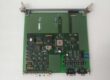
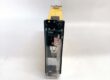
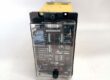
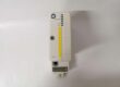
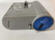
- Model: FBM203 (P0914GR)
- Alt. P/N: FBM203B (0–640Ω), FBM203C (0–30Ω), FBM203D (4-wire)
- Product Series: Foxboro I/A Series / Evo DCS
- Hardware Type: Isolated RTD input module (fieldbus)
- Key Feature: 8 fully isolated channels, Sigma-Delta ADC, 25ms per channel
- Primary Field Use: Precision temperature monitoring for critical process loops.
Hard-Numbers: Technical Specifications
- Input Channels: 8, channel-to-channel & ground isolated
- Sensor Types: Pt100, Ni120; 2/3-wire (FBM203), 4-wire (FBM203D)
- Resistance Range: 0–320Ω (std); 0–640Ω (B); 0–30Ω (C)
- Sensor Current: 0.19mA DC (std/B); 0.54mA (C)
- Accuracy: ±0.03% span; ±50ppm/°C drift
- Resolution: 16-bit (64,000 counts @ 320Ω)
- Scan Rate: 25ms per channel (Sigma-Delta)
- Isolation: 600V AC 1min channel-to-ground/channel
- Power: 24VDC (-10%/+5%); 3W max
- Operating Temp: 0°C to +60°C; G3 environment rated
- Hot Swap: Yes, online replacement
- Dimensions (W×H×D): 140×165×45mm
- Weight: ~0.6kg
The Real-World Problem It Solves
RTD readings drift or spike from ground loops, noise, and poor isolation. Generic cards lack per-channel isolation and high-resolution conversion, causing control instability and unplanned trips.
Where you’ll typically find it:
- Power plant boiler tubes, superheater/reheater temperature monitoring
- Refinery furnace, reactor, and distillation column skin temp measurement
- Chemical plant high-purity reactor and heat exchanger precision control
Delivers isolated, high-stability RTD data so operators trust readings and loops stay tight.
Hardware Architecture & Under-the-Hood Logic
FBM203 is a smart fieldbus module with per-channel Sigma-Delta ADCs; no shared multiplexer.
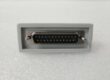
- RTD sensor connects to field terminals (2/3/4-wire).
- Per-channel 0.19mA excitation current drives RTD; lead resistance compensation applied.
- Isolated front-end filters EMI; 600V isolation blocks ground loops.
- Sigma-Delta ADC converts analog to 16-bit digital; 25ms update per channel.
- Onboard MCU linearizes, scales, and diagnostics; data sent over isolated fieldbus to controller.
Field Service Pitfalls: What Rookies Get Wrong
Mismatched RTD Wire Gauge & Lead Resistance
Over 50Ω total lead resistance or unbalanced 3-wire leads causes fixed offset and drift. Rookies use generic wire instead of matched pairs.
- Field Rule: Keep leads ≤50Ω each; use color-matched 3-wire sets; balance resistance to <0.1Ω.
Ignoring Isolation & Grounding Best Practices
Running RTD cables parallel to AC power creates common-mode noise. Symptoms: erratic jumps, 50/60Hz ripple.
- Quick Fix: Separate sensor cables >30cm from AC; never defeat channel isolation; single-point ground only.
Overlooking Configuration for Sensor Type
Using Pt100 config for Ni120, or wrong wire type, causes massive errors. Rookies copy configs without verification.
- Field Rule: Match module subtype (203/B/C/D) to sensor; set wire type (2/3/4) in logic; verify cold-junction if mixed with TCs.
Commercial Availability & Pricing Note
Please note: The listed price is for reference only and is not binding. Final pricing and terms are subject to negotiation based on current market conditions and availability.