
Description
Hard-Numbers: Technical Specifications
- Number of Output Channels: 16, isolated
- Output Signal Range: 4 to 20 mA DC
- Withstanding Voltage: 1500 V AC between output and system for 1 minute
- Allowable Load Resistance: 0 to 750 Ω
- Circuit-Open Detection: Less than 0.65 mA
- Accuracy: ±48 µA (approximately ±0.24% of 20 mA full scale)
- Data Update Period: 10 ms
- Drift due to Ambient Temperature Change: ±16 µA per 10°C change
- Maximum Current Consumption: 230 mA (5 V DC), 540 mA (24 V DC)
- Weight: Approximately 0.4 kg
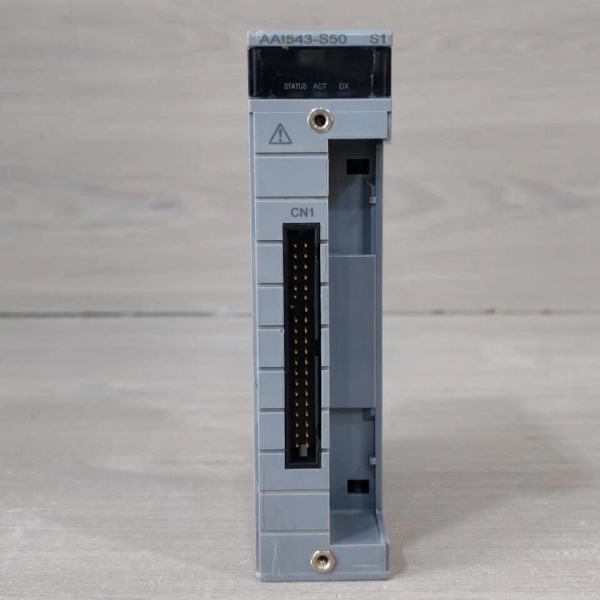
- External Connection: Pressure clamp terminal, MIL connector cable, dedicated cable (KS1)
- HART Communication: Available (when installed in ER bus node unit with HART function; firmware EB401 rev.2 or later required)
- Redundant Configuration Support: Yes (dual-redundant with two identical modules of same suffix codes)
- Switch-Over Response Time: Standard type (suffix 5) ≤ 100 ms maximum output dip below 4 mA during failover; Fast type (suffix 6) ≤ 2 ms for fast-responding field devices
- Operating Temperature: 0°C to +60°C (when suffix 6 fast switch-over type is installed in conforming temperature environment); extended temperature options available with suffix codes 1 and 3 (refer to temperature derating curves)
- Safety Compliance: Designed for process control systems; for SIL3 safety applications, use Yokogawa ProSafe-RS dedicated safety I/O modules—not this FIO module

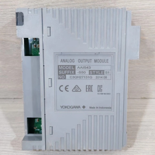
YOKOGAWA AAI543-S50
The Real-World Problem It Solves
Your distributed control system suffers from analog output signal drift, load resistor mismatch with valve positioners, and unpredictable output dips during redundant module failover causing valve positioner alarms. The AAI543-S50 eliminates these issues by delivering 16 isolated 4-20 mA outputs with ±48 µA accuracy, supporting load resistances up to 750 Ω for compatibility with most valve positioners, and providing a standard switch-over response (≤100 ms) in dual-redundant configurations that minimizes output disturbance during module failover.
Where you’ll typically find it:
- CENTUM VP Field Control Station (FCS) FIO racks for controlling control valves, actuators, and valve positioners in process control applications (oil & gas refining, chemical processing, power generation)
- ProSafe-RS Safety Control Station (SCS) for non-safety-critical analog outputs in safety instrumented systems (note: for SIL3 safety functions, use dedicated ProSafe-RS N-IO safety modules)
- Remote I/O node units (ANB10S/D, ANB11S/D) via ESB or Optical ESB bus for distributed valve control in field-mounted enclosures
- Modbus gateway or subsystem communication interfaces for interoperability with third-party PLC or SCADA systems requiring analog output channels
You get a compact, hot-swappable module with 16 isolated channels that prevents ground loops and crosstalk between outputs, dual-redundant support for high availability, and optional HART communication for digital integration with smart valve positioners and diagnostics.
Hardware Architecture & Under-the-Hood Logic
The AAI543-S50 is a 16-channel analog output module designed for Yokogawa’s FIO (Field Input/Output) architecture. Each output channel is electrically isolated from the system and from other channels, preventing ground loops and enabling direct connection to field devices without isolation barriers. The module converts digital control values from the FCS or SCS into a 4-20 mA current signal using a precision digital-to-analog converter (DAC) per channel. In dual-redundant configuration, two identical modules operate in active-standby mode with synchronized output values; upon detecting a failure in the active module, the standby module takes over control with a maximum switch-over time of 100 ms (standard type). HART communication superimposes digital signals on the 4-20 mA analog outputs, enabling bidirectional communication with HART-compatible smart devices for diagnostics, configuration, and partial stroke testing (PST) of valve positioners.
- Digital control value from FCS/SCS CPU is converted to 4-20 mA analog output by DAC per channel (16 channels)
- Output isolation barrier provides 1500 V AC isolation between each output channel and the system ground, preventing ground loops
- Current output driver delivers 4-20 mA to load resistances up to 750 Ω, compatible with most valve positioners and I/P converters
- Circuit-open detection circuit monitors output current and triggers alarm if current drops below 0.65 mA, detecting broken wires or open loops
- HART modem superimposes FSK digital signals on the analog output for communication with smart field devices (valve positioners with HART)
- Redundancy controller synchronizes output values between active and standby modules via backplane bus; failover occurs when active module fault detected
- Watchdog timer and self-diagnostics continuously monitor module health; fault status reported to FCS/SCS for alarm notification
YOKOGAWA AAI543-S50
Field Service Pitfalls: What Rookies Get Wrong
Mixing Suffix Codes in Redundant ConfigurationInstalling one AAI543-S50 (standard switch-over, no explosion protection) with a different suffix variant (e.g., AAI543-S60 fast switch-over) in a dual-redundant setup creates operational incompatibility. The two modules will have different failover response times and may not synchronize correctly, causing unexpected failover behavior or system alarms.
- Field Rule: For redundant analog output configuration, both modules must have identical suffix codes (model, switch-over response type, explosion protection rating, temperature option).
Exceeding Load Resistance LimitsConnecting field devices with total loop resistance exceeding 750 Ω causes output current to fall below 4 mA even at full scale, resulting in inaccurate valve positioning and potential “low output” alarms. This is particularly problematic when using long cable runs with high resistance or multiple devices in series.
- Quick Fix: Measure total loop resistance (valve positioner resistance + cable resistance + any series resistors) and ensure it stays below 750 Ω; use larger gauge wire or shorten cable runs if resistance is too high.
Ignoring Switch-Over Response Time for Fast DevicesUsing standard switch-over type (suffix 5) with fast-responding valve positioners that detect output dips below 4 mA within 50 ms can cause unwanted alarms or spurious trips during redundant module failover. The standard type allows up to 100 ms output dip, which may trigger fast-acting positioners.
- Field Rule: For fast-responding field devices (positioners with fast output detection), use fast switch-over type (suffix 6) which limits output dip to ≤2 ms during failover.
Improper HART Communication SetupEnabling HART communication on AAI543-S50 without ensuring the ER bus node unit firmware is at rev.2 or later results in unreliable or non-functional HART communication. The module may appear to work for analog outputs but HART commands fail intermittently.
- Field Rule: Verify ER bus node unit (EB401) firmware version before enabling HART communication; upgrade to rev.2 or later if required. HART communication is only available when module is installed in ER bus node unit with HART function.
Neglecting Circuit-Open Detection ThresholdThe circuit-open detection threshold of 0.65 mA is factory-set and non-adjustable. Some field devices or wiring configurations with small leakage currents (e.g., through water ingress or partially failed insulation) may hover near this threshold, causing intermittent “open circuit” alarms even when the loop is physically intact.
- Field Rule: If experiencing intermittent open circuit alarms with no apparent wiring breaks, measure loop leakage current with a precision milliampere meter; address insulation issues or consider if application tolerance aligns with 0.65 mA threshold.
Commercial Availability & Pricing Note
Please note: The listed price is for reference only and is not binding. Final pricing and terms are subject to negotiation based on current market conditions and availability.
- Reference Price: Approximately USD2,575.00 (retail price for AAI543-S50/A4S00 variant with pressure clamp terminal block; actual pricing may vary significantly based on supplier, quantity, and options)
- Lead Time: Typically in stock for immediate shipment; 5-7 working days for some suppliers
- Warranty: Usually 12 months from date of shipment (varies by supplier)
- Condition: New and original (factory sealed); refurbished or used options may be available at lower cost
- Availability: Widely available from Yokogawa authorized distributors and industrial automation spare parts suppliers
Reference Documents
- General Specifications: Analog I/O Modules (for FIO), GS 33K50F60-50E, Yokogawa Electric Corporation
- Product Information: Yokogawa AAI543 Analog Output Module, various suppliers (Tek-International, Quicktime Online, Runtoelectronic)
- Safety System Information: ProSafe-RS Safety Instrumented System (SIL3), Yokogawa website
- Application Notes: ProSafe-RS HART Communication with Plant Resource Manager (PRM) for Partial Stroke Testing (PST) of valve positioners
Important Note: The AAI543-S50 is designed for process control applications (CENTUM VP) and non-safety-critical outputs in ProSafe-RS systems. For safety instrumented functions requiring SIL3 compliance, use Yokogawa’s dedicated ProSafe-RS N-IO safety modules with appropriate safety certifications.


