
Description
Hard-Numbers: Technical Specifications
| Parameter | Specification |
|---|---|
| Number of Input Channels | 16, isolated |
| Input Signal Range | 4 to 20 mA DC |
| Allowable Input Current | 24 mA |
| Withstanding Voltage | Between input and system: 1500 V AC for 1 minute |
| Input Resistance | Power ON: 270 Ω (at 20 mA) to 350 Ω (at 4 mA)Power OFF: 500 kΩ or larger |
| Accuracy | ±16 μA (±0.08% of 20 mA full scale) |
| Data Update Period | 10 ms (analog data) |
| Transmitter Power Supply | 19.0 V or higher (at 20 mA)25.5 V or less (at 0 mA) (output current limit: 25 mA) |
| 2-Wire/4-Wire Transmitter Configuration | For each channel by setting pin |
| Drift due to Ambient Temperature Change | ±16 μA per 10°C |
| Maximum Current Consumption | 230 mA (5 V DC), 540 mA (24 V DC) |
| Weight | 0.3 kg (0.4 kg with pressure clamp terminal block) |
| External Connection | Pressure clamp terminal, MIL connector cable, dedicated cable (KS1) |
| HART Communication | Available (HART Protocol Revision 5.7) |
| HART Devices per Module | Max. 16 devices/module |
| HART Variables per Module | Max. 32 points/module |
| HART Multidrop Connection | Max. 5 devices/channel (input devices only, no analog data value or burst function) |
| HART Data Refresh Cycle | 1 second/device (17 seconds per ESB bus connection for 16 devices, 19 seconds for ER bus connection) |
| Analog Data Refresh with HART | Twice as much time as without HART communication (ESB: 100 ms with 2 node units, 200 ms with 4 node units, 400 ms with 6 node units; ER: 200 ms with 2 node units, 400 ms with 4 node units, 800 ms with 6 node units) |
| HART Communication Mode | Serial half duplex, start-终止 synchronization, 1 start/8 bit/odd parity/1 终止 |
| HART Transmission Speed | 1200 ±2 bps |
| HART Modulation Technique | Binary phase-continuous FSK (1: 1200 Hz ±1%, 0: 2200 Hz ±1%) |
| EB401 Firmware Requirement | Rev. 2 or later when installed in ER bus node unit with HART function |
| Isolation | Galvanic isolation per channel and between channel and system |
| Operating Temperature | 0°C to +60°C (when installed in ER bus node unit; extended temperature -20°C to +70°C available with suffix code 3) |
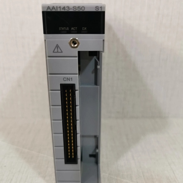
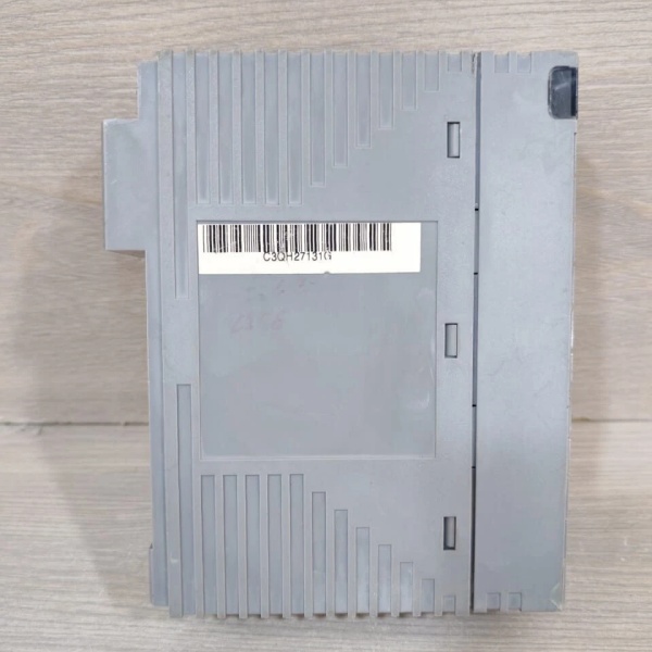
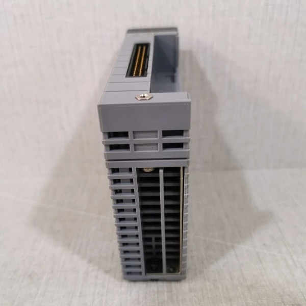
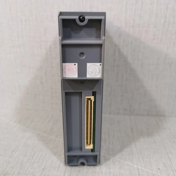
YOKOGAWA AAI143-S50
Suffix Code Breakdown
- AAI143: Analog Input Module (4 to 20 mA, 16-channel, Isolated)
- -S: Standard type
- -H: With digital communication (HART protocol)
- 5: With no explosion protection
- E: With explosion protection
- 0: Basic type
- 3: With ISA Standard G3 option and temperature (-20 to 70°C) option
- Option Code /K4A00: With KS Cable Interface Adapter for connecting AEA4D Terminal Board [Model: ATK4A-00]
- Option Code /A4S00: With Pressure Clamp Terminal Block for Analog [Model: ATA4S-00]
- Option Code /A4S10: With Pressure Clamp Terminal Block for Analog (surge absorber) [Model: ATA4S-10]
- Option Code /A4D00: With Dual Pressure Clamp Terminal Block for Analog [Model: ATA4D-00]
- Option Code /A4D10: With Dual Pressure Clamp Terminal Block for Analog (surge absorber) [Model: ATA4D-10]
- Option Code /CCC01: With Connector Cover for MIL Cable [Model: ACCC01]
HART Communication System Configuration
The AAI143-H50 module is equipped with built-in HART modems enabling digital communication with HART-enabled field devices. The HART protocol is superimposed on the 4-20 mA analog signal using Frequency Shift Keying (FSK) modulation, allowing bidirectional digital communication without additional wiring.
System Architecture:
- HART devices (transmitters, smart instruments) connect directly to AAI143-H50 input channels
- Module reads HART variables via HART Command #3 and stores them in Input/Output image area
- FCS (Field Control Station) accesses HART variables via %Z terminal connection as ordinary process input data
- Plant Resource Manager (PRM) software enables remote device diagnostics, parameter configuration, and maintenance planning
- For ER bus node units (ANR10S/D), EB401 firmware must be Rev.2 or later for HART functionality
HART Device Support:
- Maximum 16 HART devices per module
- Maximum 32 HART variables (data points) per module
- Multidrop connection: Maximum 5 HART devices per channel (input devices only)
- Supported HART Protocol: Revision 5.7 (supports HART 5, 6, and 7 devices)
- Transmission speed: 1200 bps (FSK modulation at 1200 Hz/2200 Hz)
Data Refresh Timing:
- HART variable data refresh: 1 second per device
- Total refresh time for 16 devices: 17 seconds (ESB bus) or 19 seconds (ER bus)
- Analog data refresh with HART enabled: 2x slower than without HART communication
- Response time: Max. 28 characters (256.7 ms), No response timer: 33 characters (305 ms) for primary, 41 characters (380 ms) for secondary

YOKOGAWA AAI143-S50
The Real-World Problem It Solves
Your process control system requires precise analog input from multiple HART-enabled smart transmitters distributed throughout the plant, but conventional analog input modules lack digital communication capability for diagnostics and remote configuration. The AAI143-H50 solves this by providing 16 isolated 4-20 mA current input channels with HART digital communication superimposition on each channel, enabling seamless integration with HART-compatible smart field devices (pressure transmitters, temperature transmitters, flow meters, level transmitters) while maintaining analog signal integrity for process control. The built-in HART modems eliminate the need for separate HART multiplexers, reducing wiring complexity and cost. Integration with Plant Resource Manager (PRM) enables centralized asset management, remote device diagnostics, parameter configuration, and predictive maintenance without field visits.
Where you’ll typically find it:
- CENTUM VP Field Control Station (FCS) ESB/Optical ESB/ER Bus Node Units for receiving 4-20 mA signals with HART communication from smart transmitters in process control applications (oil & gas refining, chemical processing, power generation)
- ProSafe-RS Safety Control Station (SCS) for non-safety-critical analog inputs with HART communication in safety instrumented systems (note: for SIL3 safety functions, use dedicated ProSafe-RS N-IO safety modules)
- ER Bus Node Units (ANR10S, ANR10D) for remote I/O distribution away from main control cabinet (requires EB401 firmware rev.2 or later for HART functionality)
- Plant Resource Manager (PRM) integration for remote device management, diagnostics, configuration, and predictive maintenance of HART transmitters
You get a compact, hot-swappable module with 16 isolated channels that prevents ground loops and crosstalk between inputs, dual-redundant support for high availability, built-in HART modems per channel for digital integration with smart field devices without additional multiplexing hardware.
Hardware Architecture & Under-the-Hood Logic
The AAI143-H50 is a 16-channel isolated current input module with integrated HART communication capability designed for Yokogawa’s FIO architecture. Each input channel features galvanic isolation (1500 V AC) from system ground and from other channels, preventing ground loops and common-mode noise. The module converts 4-20 mA current signals from field transmitters into digital values using a precision A/D converter per channel. For 2-wire transmitter applications, the module provides loop power (19-25.5 V DC, 25 mA limit) to power the transmitter directly. For 4-wire transmitters with separate power supply, the module measures current through an input resistor network (270-350 Ω depending on current level). Channel configuration (2-wire vs 4-wire) is set per channel via hardware setting pins on the terminal block or module connector. The built-in HART modem superimposes FSK-modulated digital signals (1200 Hz/2200 Hz) on the 4-20 mA analog signal, enabling bidirectional digital communication with HART-compatible smart devices for diagnostics, configuration, and additional process variables. HART variables are read via HART Command #3 and stored in the Input/Output image area, accessible by the FCS via %Z terminal connection and by Plant Resource Manager (PRM) software for centralized asset management. In dual-redundant configuration, two identical modules operate in active-standby mode; upon detecting a failure in the active module, the standby module takes over input acquisition seamlessly.
- Field transmitter 4-20 mA current signal enters input terminals (16 channels)
- Input protection circuit limits current to 24 mA maximum, protecting against overcurrent damage
- Input resistor network (270-350 Ω depending on current) converts current to voltage for A/D conversion
- Galvanic isolation barrier provides 1500 V AC isolation between each input channel and system ground
- Precision A/D converter digitizes voltage signal proportional to input current
- Digital value transmitted to FCS via ESB/Optical ESB or ER bus communication interface
- Built-in HART modem superimposes FSK digital communication (1200 Hz/2200 Hz) on analog signal
- HART variables read via Command #3 and stored in Input/Output image area
- FCS accesses HART variables via %Z terminal connection as ordinary process input data
- Plant Resource Manager (PRM) reads HART variables for device diagnostics, configuration, and predictive maintenance
- For 2-wire transmitters, loop power supply (19-25.5 V DC, 25 mA limit) provides power to transmitter
- Redundancy controller synchronizes input values between active and standby modules; failover upon fault detection
Field Service Pitfalls: What Rookies Get Wrong
Neglecting EB401 Firmware Version for HART CommunicationInstalling AAI143-H50 in an ER bus node unit without verifying EB401 firmware is rev.2 or later results in non-functional HART communication. The module operates correctly for analog 4-20 mA input, but HART commands fail intermittently or completely, preventing diagnostics and configuration of smart transmitters via Plant Resource Manager (PRM).
- Field Rule: Verify ER bus node unit (EB401) firmware version before installing AAI143-H50; upgrade to rev.2 or later if required for HART communication functionality.
Exceeding HART Multidrop Devices per ChannelConnecting more than 5 HART devices to a single input channel using HART multidrop splitters causes communication conflicts and unreliable HART data. The AAI143-H50 supports maximum 5 HART devices per channel, and multidrop connection only supports input devices (not analog data value or burst function).
- Field Rule: Limit HART multidrop connections to maximum 5 devices per AAI143-H50 channel; for more devices, use additional channels or dedicated HART multiplexer modules.
Ignoring HART Data Refresh Timing ConstraintsHART communication requires 1 second per device for variable data refresh. When maximum 16 HART devices are connected to one module, total refresh time is 17 seconds (ESB bus) or 19 seconds (ER bus). Rapid polling requests from host systems (PRM, DCS) can overload the HART communication channel, causing missed commands or incomplete diagnostic data from smart transmitters.
- Field Rule: Configure HART polling intervals to allow minimum 1 second per device in PRM; avoid rapid polling that exceeds module communication bandwidth.
Incorrect 2-Wire/4-Wire Transmitter ConfigurationFailing to set the correct transmitter type (2-wire vs 4-wire) via setting pins on each channel causes either no signal (4-wire transmitter connected to 2-wire configured channel) or excessive power draw (2-wire transmitter connected to 4-wire configured channel with no loop power). The setting pins are hardware configuration, not software, and must be set before connecting transmitters.
- Field Rule: Verify each channel’s setting pin configuration matches to connected transmitter type before commissioning; 2-wire transmitters require loop power from module, 4-wire transmitters have separate power supply.
Mixing Suffix Codes in Redundant HART ConfigurationInstalling one AAI143-H50 with a different suffix variant (e.g., AAI143-H53 with extended temperature) in a dual-redundant setup creates HART communication incompatibility during failover. The two modules have different operating temperature ranges and HART communication timing, potentially causing redundant module rejection during initialization or unexpected behavior during module failover.
- Field Rule: For redundant HART analog input configuration, both modules must have identical suffix codes (model, HART protocol, temperature range, explosion protection rating).
Connecting Zener Barrier to AAI143-H50 in Intrinsically Safe ApplicationsAttempting to connect a Zener barrier between AAI143-H50 module and field devices in hazardous area applications violates module specifications and causes improper operation. The AAI143-H50 module prohibits Zener barrier connection; isolation barriers must be used instead for intrinsically safe applications.
- Field Rule: Use isolation barriers (not Zener barriers) when connecting AAI143-H50 to field devices in hazardous areas requiring intrinsically safe circuits.
Misunderstanding HART Variable Data Refresh ImpactEnabling HART communication doubles the analog data refresh cycle time compared to non-HART modules. With ER bus node units, analog data refresh increases from 50 ms/100 ms/200 ms (without HART) to 100 ms/200 ms/400 ms (with HART) depending on the number of node units (2/4/6). Failing to account for this timing difference in control loop tuning can cause degraded control performance in fast-responding control loops.
- Field Rule: Adjust control loop tuning parameters (scan time, filter constants) to account for doubled data refresh time when HART communication is enabled on AAI143-H50 modules.
Commercial Availability & Pricing Note
Please note: The listed price is for reference only and is not binding. Final pricing and terms are subject to negotiation based on current market conditions and availability.
- Reference Price: Approximately USD236 for AAI143-H50/A4S00 variant with pressure clamp terminal block (retail price for AAI143-H50 without terminal block ranges from USD1,900 to USD2,200 depending on supplier; actual pricing may vary significantly based on supplier, quantity, and options)
- Lead Time: Typically in stock for immediate shipment; 1-3 working days for most suppliers with specific option codes
- Warranty: Usually 12 months from date of shipment (varies by supplier)
- Condition: New and original (factory sealed); refurbished or used options may be available at lower cost
- Availability: Widely available from Yokogawa authorized distributors and industrial automation spare parts suppliers
Reference Documents
- General Specifications: Analog I/O Modules (for FIO), GS 33K50F60-50E, Yokogawa Electric Corporation
- HART Communication Specifications: HART Communication Package (for AAI□I□□□-H), GS 33Q03L70-31E, Yokogawa Electric Corporation
- Product Information: Yokogawa AAI143-H50 Analog Input Module, various suppliers (6G Controls, Tek International, NexInstrument, Runtoelectronic)
- EB401 Firmware Requirements: Rev. 2 or later required for HART functionality when installed in ER bus node units
- Plant Resource Manager (PRM): Yokogawa asset management software for remote device diagnostics, configuration, and predictive maintenance integration with HART devices
Important Note: The AAI143-H50 is designed for process control applications (CENTUM VP) and non-safety-critical inputs with HART communication in ProSafe-RS systems. For safety instrumented functions requiring SIL3 compliance, use Yokogawa’s dedicated ProSafe-RS N-IO safety modules with appropriate safety certifications. The HART communication functionality requires EB401 firmware rev.2 or later when installed in ER bus node units.


