
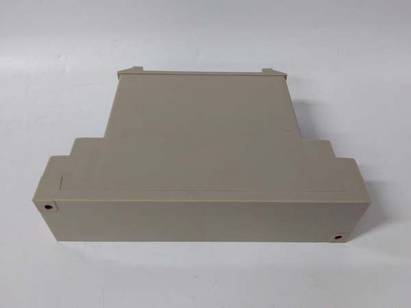
Description
Hard-Numbers: Technical Specifications
- Input Signal: Synchro/selsyn signal from YVGC-500W displacement detector (3-wire AC)
- Output Signal: DC voltage proportional to rotational angle
- Power Supply: 24 VDC (rated)
- Operating Temperature: -10°C to +55°C
- Protection Rating: IP65
- Rated Motor Current: 6A
- Servo Motor Rated Current: 15A
- Function: Synchronous rectification of synchro signal, deviation signal extraction via mixing
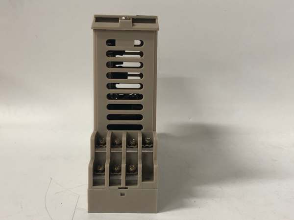
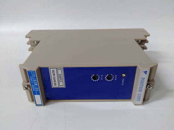
- Mounting: Rack or wall-mounted as VS system module
- Weight: Approximately 1.0-2.0 kg
- Status Indication: Power LED on front panel
- Compatibility: Designed for use with Yaskawa VS inverter drives and YVGC-500W transducers
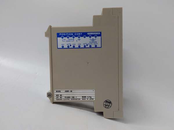
YASKAWA JGSM-06
The Real-World Problem It Solves
Legacy VS inverter systems need analog position feedback from rotary resolvers but synchro signals are AC-based and incompatible with analog drives. The JGSM-06 converts synchro/selsyn resolver signals from the YVGC-500W displacement detector into DC voltage proportional to rotational angle, enabling closed-loop position control without replacing existing resolver hardware.
Where you’ll typically find it:
- Legacy Yaskawa VS inverter drive systems with rotary position feedback requirements
- Paper machine roll position control using synchro resolvers
- Steel processing lines with angle feedback from rotary transducers
- Legacy crane and hoist positioning systems using analog DC drives
Bottom line: This module bridges old-world resolver tech to analog control systems—synchro in, DC voltage out—so you don’t have to rip out perfectly good resolver feedback just because the drive expects analog.
Hardware Architecture & Under-the-Hood Logic
The JGSM-06 is a position controller module designed for Yaskawa’s VS inverter system. It accepts synchro/selsyn AC signals from the YVGC-500W displacement detector, performs synchronous rectification to extract angular position, and outputs a DC voltage proportional to rotation angle. The module includes a signal mixing function to generate deviation signals between the reference command and actual position, essential for closed-loop control. No microprocessor here—it’s pure analog signal conditioning using precision transformers and rectifiers.
- Synchro input received from YVGC-500W displacement detector (3-wire synchro/selsyn signal)
- Scott-T transformer (internal) converts 3-wire synchro to resolver format for processing
- Synchronous rectifier demodulates AC resolver signals to DC proportional to sin/cos of angle
- Angle calculation circuitry derives rotational angle from sin/cos components
- Output amplifier generates DC voltage proportional to calculated angle
- Reference signal input enters module for deviation comparison
- Signal mixing stage calculates error between reference and actual position
- Deviation signal output goes to drive/controller for position correction
- Power supply section regulates 24 VDC input to required rail voltages
- Status LED monitors power and basic operation status
YASKAWA JGSM-06
Field Service Pitfalls: What Rookies Get Wrong
Misconfiguring Signal Mixing Gains
Techs crank deviation mixing gain too high trying to eliminate static error, causing position oscillation around setpoint. The mixing function compares reference to actual feedback—too much gain sends the servo into a hunt that wears mechanical linkages. You’ll see the system oscillating continuously, especially near commanded positions.
- Field Rule: Set mixing gain to minimum and increase incrementally. If you see oscillation, back off immediately. Position control systems need underdamped response, not zero steady-state error at the cost of stability. Oscillation kills mechanical components faster than small static error.
Using Wrong Synchro Wiring Configuration
Installers confuse synchro input connections—S1, S2, S3 get mixed up with R1, R2, R3 wiring. Synchro/selsyn signals are sensitive to phase relationships—wrong wiring reverses direction or outputs garbage. The drive responds opposite to command or doesn’t respond at all.
- Quick Fix: Verify YVGC-500W wiring diagram before connecting to JGSM-06. Label each wire at both ends during installation. If output direction is reversed, swap two of the three synchro leads (usually S1 and S3). Never power up with unknown wiring—test with a multimeter first.
Ignoring Ground Loops in Analog Output
Techs run DC analog output cable next to high-power motor leads without proper grounding. The analog output is low-level DC—noise from VFDs or motor leads injects into the signal, causing erratic position reading. You’ll see position value jitter on the drive, especially when heavy loads cycle nearby.
- Field Rule: Use twisted-pair shielded cable for analog output. Ground the shield at the controller end only—single-point grounding prevents ground loops. Route analog signals at least 12 inches away from power cables or run them in separate conduit. If you see jitter, check shield grounding first before replacing the module.
Assuming IP65 Means Waterproof Forever
Maintenance crews spray down the cabinet with water hose during cleaning, forgetting that IP65 only protects when properly sealed. The module is IP65 rated—until grommets harden, gasket cracks, or someone leaves a conduit nut loose. Water ingress kills analog circuitry.
- Quick Fix: Inspect sealing gaskets and conduit entries before wet cleaning. Replace hardened grommets annually in humid environments. Never direct high-pressure spray at module seams. IP65 is a design spec, not magic—seals degrade over time.
Forgetting Module Zero Calibration
After replacing a JGSM-06, techs skip zero calibration assuming factory default is good enough. Resolver-to-DC conversion has offset drift over temperature cycles. Uncalibrated output means zero position isn’t zero DC voltage—the system always thinks it’s off-position.
- Field Rule: Perform zero calibration after any replacement or major mechanical work. Mechanically set the resolver to zero position (referenced to equipment), then adjust the JGSM-06 zero pot (if equipped) or verify output reads 0 VDC. Document the calibration date. Zero drift matters—analog systems don’t self-correct like digital encoders.
Overloading Deviation Output
Techs connect multiple devices to the deviation signal output without buffering. The JGSM-06 deviation output isn’t designed to drive multiple inputs—loading it down causes voltage droop and inaccurate error signals. You’ll see sluggish response or position error that varies based on what else is connected.
- Quick Fix: Use a signal conditioner or buffer amplifier if you need to split deviation signal to multiple devices. Never parallel-connect high-impedance inputs directly to the output unless spec’d for it. Voltage dividers are not acceptable solutions—use proper signal distribution.
Commercial Availability & Pricing Note
Please note: The listed price is for reference only and is not binding. Final pricing and terms are subject to negotiation based on current market conditions and availability.


