
Description
Hard Numbers: Technical Specifications
- Power Supply: 12 VDC or 24 VDC (Universal range, reverse-polarity protected)
- Typical Current Draw: 100 mA (Active), 50 mA (Off/Both channels inactive)
- Speed Sensing Input: Magnetic Pickup (MPU) compatible
- Relay Outputs: 2 Independent Channels
- Switching Capacity: 1 A to 10 A (Resistive load), 1 A to 8 A (Inductive load) @ 28 VDC
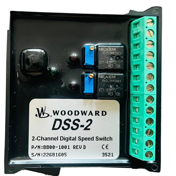
- Setpoint Adjustment: Dual multi-turn potentiometers (Manual) + PC interface (ACT tool) for advanced config
- Operating Temperature: -40°C to +85°C (-40°F to +185°F)
- Enclosure/Housing: UV-resistant, flame-retardant (UL 94 V-0), fully potted for harsh environments
- Connections: Euro-style terminal blocks
- Indicators: 3 LED indicators for status and diagnostics
The Real-World Problem It Solves
Your main governor (like a 2301D or 505) is a sophisticated computer, but what happens if its software hangs, its power supply dips, or a sensor wire vibrates loose? Without a redundant, bulletproof backup, an overspeeding engine will self-destruct in seconds.
The acts as the ultimate independent safety net. It doesn’t care about your engine’s complex control logic; it only watches the raw Magnetic Pickup (MPU) teeth flying by. If your diesel generator suddenly loses its load and the RPM skyrockets past your preset limit, the will hard-trip the fuel solenoid or opens the breaker faster than you can blink, saving hundreds of thousands of dollars in blown turbochargers or thrown rods .
Where you’ll typically find it:
- Bolted to the backplate of an emergency generator, blindly monitoring the flywheel teeth to trip the fuel shutoff if the governor fails.
- Inside the control cabinet of a natural gas compressor station, disconnecting the starter motor the exact millisecond the engine hits 700 RPM.
- On offshore drilling rigs, acting as the last line of defense (Overspeed Trip) for massive propulsion diesel engines.

WOODWARD DSS-2
Hardware Architecture & Under-the-Hood Logic
Unlike a standard relay, the is a dedicated, harsh-environment digital processing unit stripped down to do one thing perfectly: count pulses and flip relays without hesitation.
- Zero-Crossing Pulse Detection: The reads the sinusoidal AC signal from the Magnetic Pickup (MPU). It utilizes internal Schmitt triggers to clean up the noisy, amplitude-varying MPU signal into a perfect digital square wave, immune to electrical interference .
- Dual Independent Channels: It features two completely isolated processing paths. Channel 1 can be set to trip at 700 RPM (to disconnect a starter motor), while Channel 2 is set to trip at 2000 RPM (for overspeed protection). If one channel fails, the other remains fully operational .
- Manual & Digital Calibration: For standard jobs, you just twist the multi-turn potentiometers with a screwdriver. For high-precision setups, you plug a laptop into the serial port and use Woodward’s All-purpose Calibration Tool (ACT) software. This lets you dial in exact frequencies and monitor real-time RPM on a graph .
- The “Heartbeat” LEDs: The three front-facing LEDs aren’t just for show. They tell a technician instantly if the MPU signal is lost, if a relay has latched, or if the unit is actively powered, eliminating guesswork during troubleshooting .
Field Service Pitfalls: What Rookies Get Wrong
Assuming 0.0 ohms is a Good MPU Reading
Rookies use a multimeter to check the MPU (Magnetic Pickup) resistance. They see 0.0 ohms (or a dead short) and think, “Great, the coil isn’t open, the sensor must be fine.” Meanwhile, the is screaming for a “Loss of Speed Signal” trip because the internal inductance is gone, meaning the sensor can’t generate a voltage spike to trigger the zero-crossing logic.
- Field Rule: Never trust a static ohm reading on an MPU. Back-probe the sensor while the engine is cranking. You need to see at least 1 to 5 Volts AC (depending on the tooth wheel speed) on your meter. No AC voltage = dead sensor, even if the resistance reads “good”.
Setting Overspeed Too Close to Operating RPM
In a panic to meet tight emissions or load-sharing specs, rookies program the overspeed trip (Channel 2) to something reckless like 110% of operating speed (e.g., 660 RPM for a 600 RPM nominal). When the engine hits a sudden load rejection, the flywheel inertia carries it past 660 RPM, tripping the overspeed and shutting down the entire plant.
- Quick Fix: Overspeed setpoints should always account for mechanical inertia. A good rule of thumb is 115% to 120% of rated speed for mechanical diesels, and up to 125% for high-inertia gas engines. Give the governor room to catch the speed before the safety net snaps tight.
Ignoring the “ACT” Software for Fine-Tuning
Rookies rely purely on the physical potentiometers on the faceplate. They twist the screw, watch an analog voltmeter, and guess when they’ve hit the right RPM. This results in a 5-10% calibration error, which is unacceptable for precise overspeed protection.
- Field Rule: If you have a laptop, use it. Download the Woodward ACT (All-purpose Calibration Tool) software. Connect to the via the serial port. You can graphically view the exact RPM crossing the setpoint and fine-tune the pot to within 1 RPM of your target. Save the configuration file and print the screen for the site binder. If the unit ever needs replacing, you just upload the file to the new .
Commercial Availability & Pricing Note
Please note: The listed price is for reference only and is not binding. Final pricing and terms are subject to negotiation based on current market conditions and availability.


