

Description
Hard Numbers: Technical Specifications
(Note: The following specifications are compiled from typical operational parameters. Please consult the official Woodward/Cummins documentation for exact project engineering.)
- Part Number: (Cummins Cross-ref: 3044196)
- Input Voltage: 12V / 24V DC Battery Systems
- Power Consumption: 40mA (typical idle), max 4.5A output drive
- Speed Sensor Signal Input: 2 – 120V RMS (Magnetic Pickup)
- Speed Range: 1kHz – 7.5kHz (Approx. 600 – 4500 RPM depending on gear teeth)
- Actuator Output Current: 0 – 2.5A Continuous (Min. 1A, Max 4.5A for heavy-duty EFC actuators)
- Speed Stability: Better than ±0.25%
- External Speed Adjustment (Trim): ±200Hz (via external 1kΩ potentiometer)
- Operating Temperature: -40°C to +85°C (-40°F to 185°F)
- Humidity: Maximum 95% non-condensing
- Vibration Resistance: 20-100Hz at 500mm/sec
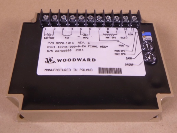
Woodward 8270-1014
The Real-World Problem It Solves
Imagine a Cummins K19 diesel engine powering a 450kW generator set at a remote mining site or a large construction project. Suddenly, a massive rock crusher or multiple air compressors kick in, drawing a huge spike of electrical load. Without an incredibly fast and precise governor, the engine would bog down, its RPM would plummet, and the generator would stall or suffer severe black smoke and mechanical stress.
The Woodward is the “quick-thinking brain” of the EFC (Electronic Fuel Control) system, designed to prevent exactly this scenario. It constantly monitors the engine’s instantaneous RPM via a magnetic speed sensor. When it detects the slightest dip or surge in speed, it processes the error and instantly adjusts the current flowing to the EFC electronic actuator, which in turn finely meters the fuel rack. This all happens in milliseconds, ensuring the engine maintains a rock-solid RPM regardless of how wildly the attached load fluctuates .
Where you’ll typically find it:
- Cummins Generator Sets: Providing prime power or standby backup in industrial plants, data centers, and remote off-grid locations .
- Marine Auxiliary Power: Governing the engines that drive shipboard generators, ensuring stable electricity for navigation and onboard systems .
- Heavy Industrial Machinery: Controlling the prime movers in mining equipment, large pumps, and oilfield fracturing fleets where engine torque and speed must be perfectly managed .
Hardware Architecture & Under-the-Hood Logic
Unlike modern fully digital “black box” controllers, the utilizes a highly refined analog-digital hybrid circuit design, making it incredibly robust and easy to troubleshoot with a basic multimeter.
- Signal Conditioning (The Ear): The controller takes the raw, often noisy sinusoidal waveform from the Magnetic Speed Sensor (MPU) mounted on the flywheel or crankshaft. It conditions this signal, filtering out electrical noise and converting it into a stable frequency that represents the real-time engine speed .
- Error Calculation (The Brain): The compares the actual engine speed against the setpoint speed (adjusted via the Speed Trim potentiometer). It calculates the “speed droop” or error. Because it is a PID-based loop, it knows not just thatthe speed is wrong, but how fastit is deviating, allowing it to anticipate and correct surging .
- Actuator Drive (The Muscle): Based on the calculated error, the controller modulates the PWM (Pulse Width Modulation) or DC current sent to the Cummins EFC actuator. An increase in current forces the actuator to pull the fuel rack towards the “max fuel” position, while a decrease in current allows the spring to pull it back to idle .
- Protection Logic: The board includes built-in safeguards against catastrophic failure. If it loses the speed sensor signal (broken wire or failed sensor), detects a short circuit in the actuator, or experiences reversed battery polarity, it will default to a safe state (usually cutting current to the actuator to allow it to return to the mechanical idle position) .
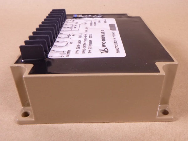
Woodward 8270-1014
Field Service Pitfalls: What Rookies Get Wrong
The “Magic Gap” Mistake (MPU Sensor Air Gap)
The relies on a clean, strong signal from the Magnetic Pickup (MPU) to calculate engine speed. Rookies often just bolt the sensor in until it touches the flywheel gear teeth and walk away.
- The Glitch: As the engine runs, thermal expansion of the block and vibration can push the sensor even tighter against the gear, eventually grinding the tip off or causing a catastrophic short. Conversely, if the gap is too wide, the signal voltage drops below the controller’s minimum threshold (usually around 1.5-2.0 Volts AC), causing the to throw a “Loss of Speed Signal” fault and shut down the engine .
- Field Rule: Always use a feeler gauge to set the MPU air gap precisely to the Cummins specification (usually between 0.25mm to 0.76mm / 0.010″ to 0.030″). Rotate the flywheel to ensure the sensor clears the highest point of every single tooth before locking it down.
Chasing Ghosts with Unstable Power Supply
Because the controls the actuator based on minute changes in voltage, it is highly sensitive to the quality of its 12V/24V DC power supply.
- The Symptom: The engine runs fine at no-load, but as soon as a heavy electrical load is applied, the RPM begins to oscillate wildly (hunt) or the controller randomly resets.
- The Cause: Voltage drop. When the generator set engages, the main starter batteries might be old or the cable runs from the battery to the controller are too thin. The sudden draw from the actuator causes the supply voltage to sag. The interprets this voltage sag as a change in actuator position and over-corrects .
- Field Rule: Always run a dedicated, thick-gauge (at least 10 AWG) power and ground wire directly from the battery terminals to the controller. Install a 10A inline fuse within 18 inches of the battery. Use a multimeter to verify the controller is actually seeing a solid 24VDC (or 12VDC) even when the actuator is drawing maximum current.
The “Dead Band” / Gain Confusion
The has internal trimpots (Gain, Stability, Droop) that rookies often blindly turn, thinking “more gain equals faster response.”
- The Consequence: If the Gain is set too high, the actuator will violently jerk back and forth, causing the engine to sound like a revving chainsaw (severe hunting). If the Gain is too low, the engine will slowly lumber along, taking 5-10 seconds to recover its RPM after a heavy load is applied .
- Field Rule: Never touch the internal trimpots unless you have an oscilloscope or a trained eye. The factory default settings are carefully calibrated for most Cummins applications. If you absolutely must adjust them, make a mark on the original position, turn the screw only 1/8th of a turn at a time, and observe the engine’s recovery for at least 30 seconds before making further adjustments.
Commercial Availability & Pricing Note
Please note: The listed price is for reference only and is not binding. Final pricing and terms are subject to negotiation based on current market conditions and availability.


