
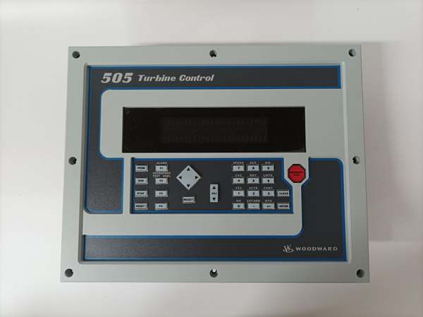
Description
Hard-Numbers: Technical Specifications
- Part Number: 9907-810
- Power Supply: 18–32 VDC (24 VDC nominal, reverse polarity protected)
- Power Consumption: 20 W typical (max 25 W)
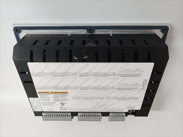
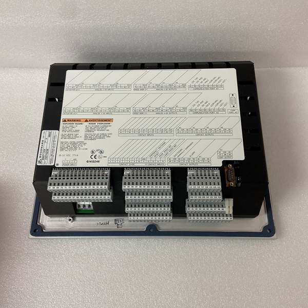
- Speed Sensor Inputs: 2 channels (Magnetic Pickup or Eddy Current, 1–100 kHz)
- Analog Inputs: 2 channels (4–20 mA, software scalable)
- Analog Outputs: 1 channel (4–20 mA, max load 500 Ω)
- Discrete Inputs: 8 channels (14–30 VDC, sourcing)
- Discrete Outputs: 4 channels (Driver outputs, 1 A max)
- Actuator Output: 1 channel (0–200 mA into 47 Ω max, or 0–400 mA option)
- Communication Ports: 1 RS-232, 1 RS-422/485 (Modbus RTU/ASCII)
- Operating Temperature: –40°C to +70°C (–40°F to 158°F)
- Weight: 1.8 kg (4.0 lb)
The Real-World Problem It Solves
Getting multiple generator sets to play nice together on a paralleled bus is a nightmare with old analog controls. The 9907-810 eliminates the unstable load swings and “hunting” caused by mechanical governors or first-gen digital units. It provides a deterministic, math-based approach to load sharing, ensuring your generators split the KW load exactly evenly without fighting each other.
Where you’ll typically find it:
- Mounted on the backplate of a 2500 kW diesel generator set in a data center, perfectly dividing the load with a sister unit during a utility outage.
- Installed in a drill rig’s power pack, managing the speed of a CAT 3516 engine driving a mud pump.
- Retrofitted into an older generator panel to replace a failing Woodward 2301A analog governor, bringing modern digital diagnostics to a legacy engine.
It keeps the frequency locked at 60 Hz and ensures the exhaust stacks aren’t smoking due to uneven fuel distribution.
Hardware Architecture & Under-the-Hood Logic
This unit is a dedicated 32-bit microprocessor designed specifically for the thermal and rotational physics of prime movers. It doesn’t run a general operating system; it executes a highly optimized control loop thousands of times per second.
- Signal Acquisition: The MPU inputs read the crankshaft speed, while the analog inputs pull in the generator’s KW load signal (via CT/PT or from a separate meter).
- Error Calculation: The CPU compares the actual speed to the “Rated Speed” setpoint. It also calculates the speed offset required to achieve the desired load percentage.
- PID Processing: The error signal hits the Proportional-Integral-Derivative block. The 2301D is unique because it features a “non-linear gain” algorithm—it applies aggressive correction during large transients (like a sudden block load) and softens the gain as it nears the setpoint to prevent overshoot.
- Actuator Drive: The processed signal is converted to a high-resolution current output (0-200mA), which drives the Woodward actuator (like an EG-3P or UG-40) to physically move the fuel rack.
- Communications Co-Processor: A secondary chip handles the Modbus traffic, ensuring that a noisy RS-485 line doesn’t interrupt the critical speed control loop.
Woodward 9907-151
Field Service Pitfalls: What Rookies Get Wrong
Ignoring the “Failed Speed Override” Logic
When the 2301D loses its speed sensor signal (MPU failure), it defaults to a pre-programmed “Failed Speed” setpoint. Rookies often forget to configure this safety net. If the sensor wire vibrates loose, the engine suddenly thinks it’s at 0 RPM and slams the fuel rack to full open, causing an overspeed trip or catastrophic damage.
- Field Rule: Always program the “Failed Speed Override” to a safe, known value (e.g., 95% of rated speed). Physically tug on the MPU wires during commissioning to simulate a failure and verify the engine droops or trips safely.
Wrong MPU Tooth Count or Gear Pitch
Technicians often assume the speed sensor settings are universal. If you replace a 113-tooth ring gear with a 142-tooth gear but don’t update the 2301D’s software configuration, the speed reading will be off by 20%. The governor will think it’s running slow and over-fuel the engine.
- Field Rule: Count the teeth on the flywheel gear. Log into the 2301D configuration menu and verify the “Teeth per Revolution” parameter matches the physical hardware. Double-check this against the nameplate on the magnetic pickup.
Chasing Ghosts Caused by Noisy 4-20mA Signals
The 2301D relies on a clean 4-20mA signal from the load sensors for isochronous load sharing. Rookies often run the shielded twisted pair (STP) for this signal in the same conduit as the 480VAC generator output cables. The induced electrical noise makes the load reading jump wildly, causing the engines to fight each other (hunt) on the bus.
- Field Rule: Keep all analog signal wires at least 12 inches away from high-voltage AC wiring. Ensure the shield is tied to earth ground at the 2301D end only. Never use the shield as a current-carrying conductor.
Commercial Availability & Pricing Note
Please note: The listed price is for reference only and is not binding. Final pricing and terms are subject to negotiation based on current market conditions and availability.


