
Description
Hard Numbers: Technical Specifications
- Operating Voltage: 18–40 Vdc (24 Vdc or 32 Vdc nominal)
- Power Consumption: 40 W (Typical)
- Inrush Current: 7 A @ 0.1 ms
- Speed Sensor Inputs: 2 Channels (Magnetic Pickup or Proximity Probe)
- Analog I/O: 4 Inputs (Configurable ±5 V or 0–20 mA) / 3 Outputs
- Discrete I/O: 8 Inputs / 3 Outputs (Relay or Transistor)
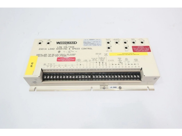
- Communication Ports: RS-232, RS-422, RS-485 supporting Modbus (ASCII/RTU) and LON protocols
- Operating Temperature: -40°C to +70°C (-40°F to 158°F)
- Humidity Tolerance: 95% at +20°C to +55°C
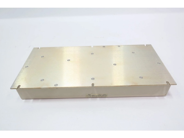
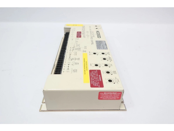
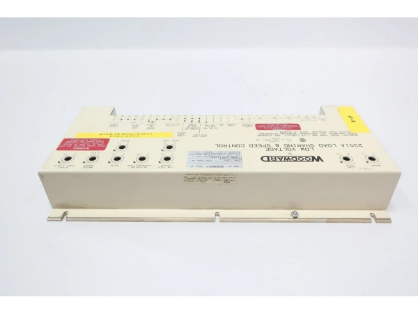
- Physical Construction: Sheet metal chassis with integrated PCB
The Real-World Problem It Solves
Mechanical flyball governors are obsolete technology. They suffer from mechanical wear, causing speed drift and load instability. When you need precise load sharing between multiple generators or tight speed control on a gas compressor, old mechanical linkages are a liability. The 9907-247 replaces that aging hardware with a solid-state, software-configurable control platform. It eliminates the physical slack in your fuel system and provides a stable, repeatable RPM lock while communicating directly with modern plant DCS or PLC systems.
Where you’ll typically find it:
- Mounted in the control cabinet of a standby generator set, managing the gas fuel valve and throttle actuator.
- Controlling the speed of diesel-driven fire water pumps in refinery applications where reliability is non-negotiable.
- Installed on marine auxiliary engines, integrating via Modbus to the ship’s central monitoring system.
It takes the guesswork out of engine tuning and automates the start, stop, and load acceptance sequences.
Hardware Architecture & Under-the-Hood Logic
This unit is a dedicated 32-bit microprocessorbased closed-loop controller. It doesn’t rely on a host PC to function; it reads sensors, executes control laws, and drives hardware autonomously.
- Signal Acquisition: The module continuously samples two independent speed sensors (MPUs) to calculate real-time RPM. It also scans the 4 analog and 8 discrete inputs to monitor system status (oil pressure, coolant temperature, shutdown signals).
- Control Law Execution: Based on the selected mode (Speed Control, Load Control, or Droop), the CPU calculates the required actuator position to maintain the target setpoint.
- Actuator Drive: The processor generates a precise command signal (via the 3 analog outputs or discrete outputs) to drive the connected actuator or I/P converter, adjusting the fuel rack or guide vanes.
- System Protection & Comms: It constantly monitors for fault conditions (Overspeed, underspeed, sensor loss). If a trip condition occurs, it triggers the shutdown outputs immediately. All operational data is simultaneously broadcasted over the RS-485 or LON network for plant monitoring.
Field Service Pitfalls: What Rookies Get Wrong
Improper MPU (Magnetic Pickup) Air Gap
Rookies install the speed sensor using the “finger tight plus a quarter turn” method. If the gap between the sensor tip and the gear teeth is too wide, the induced AC voltage drops, especially during engine crank. The controller loses track of the RPM, assumes a runaway condition, and slams the fuel to zero, causing a failed start.
- Field Rule: Use a multimeter. Crank the engine (fuel off) and measure the AC millivoltage at the MPU terminals. Adjust the sensor until you see a clean, strong sine wave, typically between 1.5V and 5V AC at cranking speed. Lock it down and recheck.
Voltage Sag During Transient Loads
The 9907-247 pulls significant current when initializing or when the display backlight is on. Rookies tap into a shared 24V bus that also powers solenoids and indicator lights. When a large contactor pulls in, the voltage at the 9907-247 dips below 18V. The module interprets this as a power loss, resets, and drops the actuator to the “fuel off” position.
- Quick Fix: Run a dedicated 14 AWG (or larger) pair directly from the battery terminals or a dedicated power distribution block to the 9907-247. Install a 10A slow-blow fuse in the positive lead right at the power source. Do not share this fuse with anything else.
Ignoring the Second Speed Sensor (Redundancy Loss)
In critical applications, the 9907-247 supports two MPUs for redundancy. Rookies often only wire one because “one is working fine.” Six months later, that single sensor fails due to vibration fatigue. The engine instantly trips on “Speed Sensor Loss,” bringing down the entire process line.
- Field Rule: If the application manual calls for dual MPUs, install them both and wire them to the 9907-247. During commissioning, intentionally disable the primary sensor to verify the controller seamlessly switches to the backup sensor without tripping the engine.
Commercial Availability & Pricing Note
Please note: The listed price is for reference only and is not binding. Final pricing and terms are subject to negotiation based on current market conditions and availability.


