
Description
Hard-Numbers: Technical Specifications
- Input Voltage: 18–32 Vdc (24VDC nominal), approximately 5 W power consumption
- Operating Temperature: -40°C to +70°C
- PT Input Burden: 1.6 W per phase at 240 Vac, 0.4 W per phase at 120 Vac
- CT Input Burden: 0.1 VA per phase at full load (3-7 Arms)
- Speed Control Output: +0.5 to +4.5 Vdc analog, ±3 Vdc analog, or PWM (model dependent)
- Isolation Rating: Overvoltage Category III
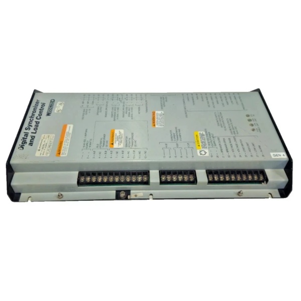
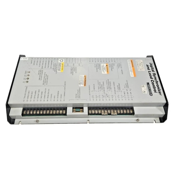
- Physical Dimensions: 273.6 mm (L) x 214.1 mm (W) x 59.2 mm (H)
- Shock Rating: 40 G, 11 ms sawtooth pulse
Woodward 9905-797
The Real-World Problem It Solves
Paralleling generators without a dedicated load sharing module is a recipe for disaster. You’ll end up with one unit hogging the entire block load while the other struggles at the brink of stalling. The 9907-175 eliminates this by continuously monitoring real-time CT and PT inputs, then outputting a corrective signal to the speed control to ensure wattage is split exactly where it’s needed.
Where you’ll typically find it:
- Mounted in the control cabinet of paralleled diesel or gas generator sets in data centers and hospitals.
- Integrated into switchgear panels coordinating multiple utility tie-breakers and backup gensets.
Bottom line: It prevents circulating currents and unstable frequency drift when multiple power sources fight to carry the same load.
Hardware Architecture & Under-the-Hood Logic
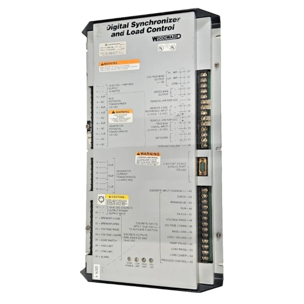
This module is a dedicated analog/digital hybrid processor designed to sit between your generator’s potential transformers (PTs), current transformers (CTs), and the engine’s speed governor. It calculates real power output and adjusts the speed setpoint accordingly.
- Continuously samples 3-phase voltage (PT) and current (CT) inputs to calculate the generator’s true real power (kW).
- Compares this calculated load against the user-defined Load Gain setpoint and the external Droop adjustment.
- Generates a dynamic correction signal—either as an analog DC voltage (+0.5 to +4.5 Vdc) or a Pulse Width Modulated (PWM) signal—depending on the specific model configuration.
- Sends this output directly to the engine’s speed control or actuator, nudging the throttle to increase or decrease fuel delivery.
- Monitors synchronization signals (compatible with Woodward SPM-A) to ensure seamless transition when closing the breaker to an infinite bus.
Field Service Pitfalls: What Rookies Get Wrong
CT Phase Mismatch (The “Reverse Power” Trip)
If the current transformers (CTs) are wired out of phase with the potential transformers (PTs), the module will calculate negative power. This causes the governor to drive the engine in the opposite direction, leading to immediate reverse power trips or outright instability.
Quick Fix: Perform a temporary phase correction check before finalizing the plant wiring. Swap any two CT secondary leads if the load signal drives the speed control the wrong way during a no-load test.
Improper Droop Setting on the Potentiometer
Guys often max out the droop adjustment thinking it will provide more stable load sharing. In reality, excessive droop makes the generator sluggish and unable to pick up its fair share of a sudden block load.
Field Rule: For isochronous operation (tight frequency control), ensure the Droop switch is closed (auxiliary contact active). If operating in droop mode, set the potentiometer to achieve a frequency drop of no more than 3% to 5% from no-load to full-load.
Chasing a Clean Speed Trim Signal
The 9907-175 relies on a very sensitive 0-5Vdc speed trim input from the external potentiometer or master controller. Running this low-voltage signal in the same conduit as high-voltage 480V generator cables introduces noise that wreaks havoc on the PWM output.
Field Rule: Always route the speed trim and load share lines in shielded, twisted-pair cable, grounded at the module end only. Keep it physically separated from AC power wiring by at least 6 inches.
Woodward 9905-797
Commercial Availability & Pricing Note
Please note: The listed price is for reference only and is not binding. Final pricing and terms are subject to negotiation based on current market conditions and availability.


