
Description
Hard-Numbers: Technical Specifications
- Input Signal: 4-20 mA DC isolated (250 Ω input impedance)
- Output Pressure: 0-10 bar / 0-145 psi (Zone 2 configuration)
- Maximum Supply Pressure: 25 bar / 363 psi
- Supply Pressure Range: 20-30 psi recommended minimum for operation
- Return/Drain Pressure: Maximum 2 bar / 29 psi
- Accuracy: < ±0.2% of full range
- Repeatability: 0.1% of full range
- Temperature Drift: < ±0.01% of full range per °C
- Pressure Stability: < ±2% of setpoint
- Input Power Supply: 18-32 V DC @ 1.5 A steady-state, 8 A peak (100 ms)
- Analog Output: 4-20 mA (300 Ω maximum external load, ±1% accuracy)
- Discrete Inputs: Optically isolated (24 V DC wetting voltage required)
- Discrete Outputs: 1 A @ 30 V DC (alarm and shutdown relay outputs)
- Service Tool Port: RS-232 serial communication (straight-through cable)
- Operating Temperature: -40°C to +85°C
- Hydraulic Oil Temperature: 15-70°C
- Oil Viscosity: 20-100 cSt recommended
- Oil Filtration: 24-40 μm nominal, β75 or ISO 20/16 Class recommended
- Specific Gravity: 0.6-1.0 (mineral or synthetic oils)
- Air Consumption: 0.5 SCFM at 20 psi
- Dimensions: Approximately 290 mm × 270 mm × 270 mm
- Weight: Approximately 25 kg (55 lb) without oil
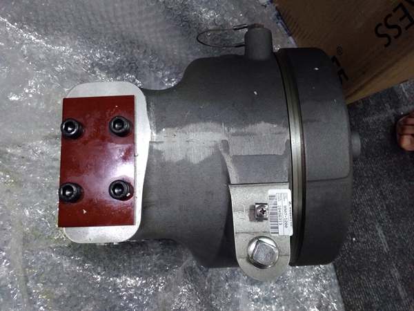
- Mounting: Four M10 threaded holes, 23 mm deep, on face with hydraulic ports (any attitude)
- Shock: 10 G peak, 11 ms duration (US MIL-STD-810C method 516.2, procedure 1)
- Vibration: 1.04 G_rms, 10-500 Hz (US MIL-STD 810F, M514.5A, Cat. 4)
- Ingress Protection: IP66 per EN 60529
- Compliance:
- ATEX: Zone 2, II 3 G Ex nA IIC T4 Gc (SIRA 11ATEX1310X)
- IECEx: Zone 2, Ex nA IIC T4 Gc (IECEx CSA 11.0017X)
- EAC Customs Union: Ex nA IIC T4 Gc X (CU 012/2011)
- CSA: Class I, Div. 2, Groups A, B, C, D, T4 at 85°C (LR46653)
- CE, EMC (EN61000-6-2 immunity, EN61000-6-4 emissions)
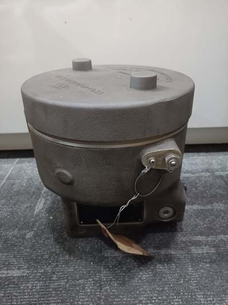
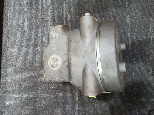
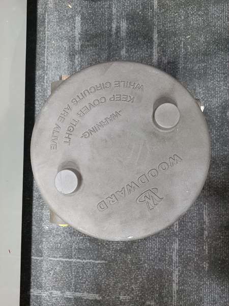
WOODWARD 9907-1200
The Real-World Problem It Solves
Dirty hydraulic oil in steam turbine governor systems causes servo valve spools to hang, pressure output drifts, and eventually the unit fails—resulting in turbine trips, lost generation capacity, and emergency shutdowns during peak demand. The 9907-1200 eliminates contamination-related failures with a self-cleaning “Silt Buster” program, redundant controller inputs for failover operation, and 11-point linearization for valve nonlinearity compensation. Your governor oil can carry particles that would cripple conventional I/P converters—this unit keeps turbines online through contaminated oil conditions.
Where you’ll typically find it:
- Industrial steam turbine-driven generator sets (10-100 MW) in power plants requiring single-acting governor valve positioning
- Steam turbine mechanical drive applications (pumps, compressors) with electro-hydraulic control systems in Zone 2 hazardous areas
- Refinery and petrochemical plant steam turbines where oil contamination is unavoidable and redundancy is critical for continuous operation
Bottom line: This current-to-pressure converter is your contamination-resistant governor workhorse—redundant inputs keep turbines running during controller failures, self-cleaning design survives dirty oil, and ±0.2% accuracy maintains precise speed/load control in harsh industrial environments.
Hardware Architecture & Under-the-Hood Logic
The 9907-1200 is an electro-hydraulic CPC-II (Current-to-Pressure Converter, Generation II) that accepts 4-20 mA electronic demand signals and converts them to proportional hydraulic output pressure (0-10 bar) for single-acting steam turbine servo valves. The unit features a powerful actuator with a single-moving rotary valve design and corrosion-resistant materials for harsh environments. Redundant controller inputs (master/slave or dual-redundant modes) provide automatic failover. The internal microprocessor applies an 11-point linearization table to compensate for valve flow nonlinearity. A “Silt Buster” program cycles the valve to clear accumulated contamination in slave units during redundant operation. Hydraulic oil flows through internal filtration and pressure regulation stages, converting electrical current signals to precise oil pressure. Discrete inputs and outputs provide alarm and shutdown capabilities, while the analog output channel reports control oil pressure level to the system controller or plant DCS. Configuration and calibration are performed via a service tool port using RS-232 communication.
- Power-up sequence: 18-32 V DC supply energizes; microprocessor initializes and performs self-test
- Input signal acquisition: 4-20 mA demand signal enters through isolated input circuit (250 Ω impedance)
- Redundancy check: Unit checks redundant controller inputs; switches to backup if primary fails (master/slave or dual-redundant modes)
- Linearization application: Microprocessor applies 11-point linearization table to compensate for valve flow nonlinearity
- Actuator positioning: Single-moving rotary valve adjusts based on linearized demand signal
- Hydraulic pressure generation: Internal hydraulic pump/regulator converts valve position to output pressure (0-10 bar)
- Silt Buster activation: In redundant slave applications, valve cycles periodically to clear accumulated contamination
- Pressure feedback: Internal pressure sensor monitors output pressure; 4-20 mA analog output reports to DCS
- Alarm monitoring: Microprocessor checks for abnormal conditions; triggers discrete outputs (alarm/shutdown relays)
- Service tool communication: RS-232 port allows configuration, calibration, and PID adjustment via computer-based PCI tool
WOODWARD 9907-1200
Field Service Pitfalls: What Rookies Get Wrong
Ignoring Oil Filtration Requirements and Introducing Contamination
Techs connect 9907-1200 directly to turbine hydraulic oil supply without proper filtration, assuming “new oil is clean enough.” Hydraulic oil carries metal particles, seal debris, and slurry from gearboxes—bypassing 24-40 μm filtration allows contaminants to enter the servo valve, causing spool hang, pressure drift, and eventual actuator seizure. You’ll see erratic pressure output, hunting governor behavior, and premature servo failure.
- Field Rule: Install proper filtration upstream of the 9907-1200. Use 24-40 μm nominal filtration with β75 rating or ISO 20/16 Class. Verify filter condition during turbine outages—replace if bypass indicator shows. Never install new I/P converters without verifying filtration. Dirty oil kills precision hydraulic components faster than mechanical wear—filtration is mandatory, not optional.
Misconfiguring Redundant Inputs and Losing Failover Protection
Engineers wire both redundant controllers to the same CPC input terminals, creating single points of failure instead of true redundancy. When primary controller fails, backup can’t take over because both inputs see the same failed signal path. You’ll experience turbine trips during controller failures that should have been transparent switchovers.
- Quick Fix: Configure redundant inputs per Woodward manual—master/slave mode uses one CPC with two controller inputs, or dual-redundant mode uses two CPCs with cross-connected inputs. Verify wiring matches redundancy schematic. Use service tool to enable and test failover during commissioning. Redundant wiring matters—single-point failures defeat redundant design. Test switchover before relying on it for production.
Exceeding 70% Output Pressure Rule and Losing Dynamic Performance
Operators set output pressure too close to supply pressure (e.g., 9 bar output with 10 bar supply), ignoring the “less than 70% of supply” recommendation. At high output ratios, dynamic response degrades—valve can’t open fast enough for load changes, causing speed oscillations and instability during ramping. You’ll see governor hunting during load steps and potential overspeed trips.
- Field Rule: Maintain output pressure below 70% of supply pressure for best dynamic performance. For 25 bar supply, keep output below 17.5 bar. If higher output is required, increase supply pressure, not output setpoint. Dynamic response depends on pressure differential—high output ratios starve the actuator. Check supply pressure versus output setpoint during commissioning.
Neglecting “Silt Buster” Configuration in Redundant Slave Units
Techs install redundant 9907-1200 units but fail to enable “Silt Buster” program on slave units. Slave units sit idle for months while master runs all the time—contaminants accumulate in slave servo spools, causing failover to fail when primary controller goes offline. You’ll test redundancy during planned outages and discover slave unit hangs or has erratic output.
- Quick Fix: Use PCI service tool to configure “Silt Buster” program on slave units. Set appropriate cycle frequency (typically weekly or monthly). Verify slave unit cycles during scheduled testing. Redundant slaves need exercise to prevent contamination buildup—idle units fail when called upon. Configure Silt Buster during commissioning, not during emergencies.
Over Tightening Hydraulic Fittings and Cracking Aluminum Housing
Mechanics crank down on hydraulic fittings to 终止 leaks, exceeding torque specifications on the aluminum housing. The 9907-1200 housing is aluminum—over-torquing cracks the casting near port threads, creating leaks that can’t be fixed with thread sealant. You’ll discover weeping hydraulic oil during turbine outages and eventually lose pressure during operation.
- Field Rule: Use torque wrench on hydraulic fittings—refer to Woodward manual for specific torque values (typically 30-50 ft-lbs for hydraulic ports). Never tighten beyond spec to 终止 minor weeping—use proper thread sealant (Loctite 577 or equivalent) instead. Cracked housings mean replacing the entire unit—expensive compared to sealant. Aluminum cracks propagate—catch over-torqued fittings during installation, not after leaks appear.
Forgetting to Isolate Supply During CT Phasing Checks
Electricians measure current transformer voltages at load sensor terminals while generator is running, without installing temporary 1 Ω, 5 W resistors as specified in the manual. Open-circuited CTs develop dangerously high voltages—personnel risk arc flash injury, and insulation fails on control terminals. You’ll damage the 9907-1200 input circuit and create safety hazards during calibration.
- Field Rule: Before disconnecting CT wires, install temporary 1 Ω, 5 W resistors across CT secondaries. Verify resistors are in place before opening CT connections. Never measure or disconnect CTs while generator is running without shorting. Open CTs kill—high voltage kills both people and equipment. Treat CTs with same respect as primary voltage—short before touching.
Mixing Oils with Incompatible Viscosity and Starving the Pump
Maintenance crews top up hydraulic reservoir with whatever oil is in inventory, ignoring viscosity range (20-100 cSt). Too-thick oil won’t flow at cold start, causing pump cavitation and delayed pressure response—too-thin oil provides inadequate lubrication, causing actuator wear. You’ll see slow governor response on cold startups and increased servo wear over time.
- Quick Fix: Use only hydraulic oils meeting 20-100 cSt viscosity range at operating temperature. Verify oil specs before adding to reservoir. Mix compatible oils only—consult compatibility charts if changing oil types. Governor hydraulics demand specific viscosity—wrong oil kills pumps and actuators. Keep oil samples from commissioning for reference during maintenance.
Commercial Availability & Pricing Note
Please note: The listed price is for reference only and is not binding. Final pricing and terms are subject to negotiation based on current market conditions and availability.


