
Description
Key Technical Specifications
-
Model Number: 9907-014
-
Manufacturer: Woodward Inc.
-
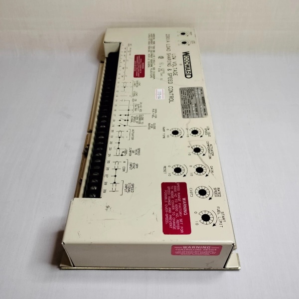
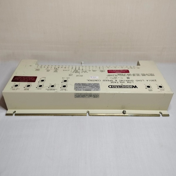
Product Family: 2301A Load Sharing and Speed Control (LSSC)
-
Revision: REV H (as noted in some listings)
-
Power Supply: 10-40 V DC (Low Voltage Model)
-
Power Consumption: ≤15 W
-
Actuator Output: 0-200 mA current signal
-
Actuation Type: Forward-acting, single actuator
-
Speed Sensing: Magnetic Pickup Unit (MPU), 1.0 Vac minimum to 30 Vac maximum
-
Speed Sensor Input Impedance: 100-300 Ω
-
Speed Ranges (Switch-Selectable): 500-1500 Hz, 1000-3000 Hz, 2000-6000 Hz (standard), 4000-12000 Hz
-
Control Modes: Isochronous or Droop (selectable via external switch/relay)
-
Full Authority Speed Setting: 4-20 mA or 1-5 Vdc input signal
-
Load Sharing: Self-contained load sensor with 0-6 Vdc analog load-sharing lines
-
Operating Temperature: -40°C to +85°C (-40°F to +185°F)
-
Storage Temperature: -40°C to +70°C
-
Dimensions: 8.625″ W × 7.25″ H × 2.5″ D (219 × 184 × 64 mm)
-
Weight: 2.5 lbs (1.13 kg) / 2 lb 8 oz
-
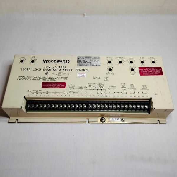
Enclosure: Sheet-metal chassis with single PCB architecture
-
Start Fuel Limiting: Automatic, adjustable to reduce emissions and engine wear
-
Compliance: EU Directive Compliant (CE Marked)
-
Compatibility: Woodward SPM-A Synchronizers, AGLC, APTL, Import/Export Controls

WOODWARD 9905-020P
Field Application & Problem Solved
In the field, the biggest challenge with multi-generator installations is maintaining stable frequency while ensuring equal load distribution across units—especially in European markets where CE compliance is mandatory. Without proper load sharing, one genset ends up carrying the bulk while others “motor” or fight each other, creating thermal stress, fuel inefficiency, and potential reverse power trips. The 9907-014 solves this by providing true isochronous load sharing through analog load-sharing lines that balance kW output proportionally across all units in the system, while meeting EU electromagnetic compatibility and safety directives.
You will typically find this controller in power generation applications requiring CE marking—think European offshore platforms, EU-flagged marine vessels, European industrial cogeneration plants, and export-oriented generator packages. It’s particularly common on Caterpillar, Waukesha, and Cummins engine packages destined for European markets where the non-compliant 9905-131 cannot be used. The 9907-014 is functionally identical to the 9905-131 but carries the required CE marking and meets EU directive requirements for electromagnetic compatibility and safety.
Its core value is maintaining bus frequency within ±0.25% of rated speed while seamlessly transitioning between isochronous mode (isolated bus operation with load sharing) and droop mode (utility parallel or infinite bus operation). The integrated load sensor eliminates the need for external load sensors—this control measures generator current and voltage internally, calculates real power, and generates the load-sharing signal. The 4-20mA or 1-5Vdc full authority speed setting
is a key differentiator from basic 2301A models; it allows remote SCADA systems or process controllers to command speed setpoint over the full range, not just trim. The automatic start fuel limiting is another field-saver; it caps maximum fuel during startup to prevent wet stacking in diesels or over-firing in gas engines. For technicians, the all-front-access potentiometer design means you can tune gain, stability, and droop without pulling the unit from the panel—a significant advantage when you’re working in cramped switchgear rooms.
Installation & Maintenance Pitfalls (Expert Tips)
EU Compliance Doesn’t Mean “Plug and Play”
A common field mistake is assuming the 9907-014’s CE marking makes it interchangeable with any European system. While it meets EMC directives, you still need to verify your actuator direction, PT configuration, and grounding scheme. The 9907-014 is specifically forward-acting (0-200 mA output where increasing current increases fuel)
. If you’re retrofitting this onto a reverse-acting actuator setup, the engine will slam to minimum fuel when it should be starting. Check your actuator part number against Woodward’s compatibility matrix. The reverse-acting EU-compliant equivalent is the 9907-016 (matching 9905-133).
. If you’re retrofitting this onto a reverse-acting actuator setup, the engine will slam to minimum fuel when it should be starting. Check your actuator part number against Woodward’s compatibility matrix. The reverse-acting EU-compliant equivalent is the 9907-016 (matching 9905-133).
4-20mA Speed Setting vs. Remote Speed Setting Are Different
The 9907-014 has two distinct speed reference inputs: the full authority 4-20mA/1-5Vdc setting (terminals typically 23-24) and the raise/lower speed setting (terminals 25-26). Rookies often wire their SCADA system’s 4-20mA output to the raise/lower terminals, expecting full range control but only getting ±10% trim. Conversely, wiring a simple contact closure speed trim to the full authority input causes the engine to hunt wildly as it tries to follow the noisy contact signal. Verify your wiring against the terminal diagram in manual 82389. The full authority input is for remote SCADA setpoint; the raise/lower is for local panel switches or slow-speed process control.
Load-Sharing Line Terminations Are Critical
The analog load-sharing lines (terminals 10 positive, 11 negative) must be wired in parallel across all units with proper shielding. I’ve seen installations where the shield was grounded at both ends, creating ground loops that introduced 50 Hz hum (in 50 Hz European systems) into the load-sharing signal. This manifests as erratic kW hunting between units—one genset surging while another sags. Ground the shield at terminal 12 (control end only), and keep the load-sharing wiring twisted-pair, separate from high-current power cables. When mixing 9907-014 controls with other Woodward systems, do not connect shields at the load-sharing bus junction.
Droop vs. Isochronous Switch Wiring
The mode selection depends on terminal 14 being connected to terminal 16 (common) for isochronous, or opened for droop. Many field issues stem from improper auxiliary contact wiring from the circuit breaker. If you’re paralleling with the utility, you need droop mode; if you’re on an isolated bus with other Woodward controls, you need isochronous. I’ve seen plants where the breaker auxiliary contact was wired backwards, causing the unit to run isochronous into the grid—resulting in immediate reverse power trips or instability. Verify your breaker contact logic with a multimeter before commissioning. Remember: both droop contact AND breaker contact must be closed for isochronous load sharing.
Speed Sensor Phasing and Gap
The MPU input is sensitive to phasing. While the control will typically “run” with reversed leads, you’ll see erratic speed readings and poor stability. If your speed indication jumps around or the control hunts excessively, swap the MPU leads at terminals 28 and 29. Also, ensure your MPU gap is set correctly—typically 0.020 to 0.030 inches for standard magnetic pickups. Too wide a gap gives weak signal; too close risks contact damage from shaft runout. At starting speed, you need minimum 1.0 Vrms; at rated speed, maximum 30 Vrms
. If you exceed 30V at rated speed, increase the gap immediately to prevent control damage.
CT Polarity Determines Load Sharing Direction
The current transformer connections must be phased correctly for the load sensor to work. If your CTs are reversed, the control will see negative load and try to “correct” by adding fuel, causing runaway or reverse power conditions. During commissioning, verify that increasing generator load shows increasing voltage on the load-sharing lines (terminals 10-11). If load increases but the voltage decreases, swap your CT leads. The standard connection is Wye, though open-delta is acceptable for some applications.
Shielded Cable Installation is Non-Negotiable
All cables connecting the control to the engine must be shielded twisted pair. Never attempt to solder the woven shield—this can cause serious injury and cable failure. Use proper cable glands and ground the shield to the chassis ground plate for true earth grounding. In European installations with strict EMC requirements, improper shielding will result in control malfunction and failure to meet CE compliance.
WOODWARD 9905-020P
Technical Deep Dive & Overview
The Woodward 9907-014 is an analog load sharing and speed control module from the 2301A series, representing the EU Directive Compliant variant of the mature 2301A architecture. It consists of a single printed circuit board housed in a rugged sheet-metal chassis, with all tuning potentiometers accessible from the front panel—no software interface, no programming cables, no firmware revisions to track. This analog simplicity is both a limitation and a reliability advantage in harsh environments where network-based controls might fail.
The control operates as a closed-loop speed regulator with an inner current loop driving a proportional actuator. Speed feedback comes from a magnetic pickup unit sensing gear teeth on the engine flywheel or accessory drive, converted internally from frequency to voltage via a discriminator circuit. This speed signal is compared against a reference (set by front-panel SPEED ADJUST potentiometer, external 4-20mA signal, or 1-5Vdc input), with the error amplified and conditioned through GAIN and STABILITY (reset) networks before output to the actuator driver stage. The 0-200 mA output is a current source, not a voltage source—this provides better noise immunity and consistent torque from the actuator regardless of wiring length.
The full authority speed setting capability
distinguishes the 9907-014 from basic 2301A models. The 4-20mA or 1-5Vdc input (terminals 23-24) allows an external controller or SCADA system to command any speed from idle to rated, not just trim around a setpoint. This is essential for variable speed applications like pump jacks, compressors, or process-controlled generators. The raise/lower inputs (terminals 25-26) remain available for slow-speed contact closure control.
distinguishes the 9907-014 from basic 2301A models. The 4-20mA or 1-5Vdc input (terminals 23-24) allows an external controller or SCADA system to command any speed from idle to rated, not just trim around a setpoint. This is essential for variable speed applications like pump jacks, compressors, or process-controlled generators. The raise/lower inputs (terminals 25-26) remain available for slow-speed contact closure control.
The load sharing function operates through an analog current loop between paralleled units. The 9907-014 contains an internal load sensor that measures generator current (via CTs) and voltage (via PTs), calculates real power using analog multipliers, and generates a 0-6 Vdc signal representing load magnitude. This voltage is shared across the parallel load-sharing lines (terminals 10-11). The control adjusts its speed reference slightly to equalize these voltages, resulting in proportional kW sharing without master/slave hierarchy. The load-sharing-line relay (internal to the control) energizes when both the droop contact and breaker auxiliary contact are closed, connecting the load-matching circuit to the system.
From a system architecture perspective, the 9907-014 functions as the primary fuel control authority, receiving permissive and mode commands from external switches (idle/rated, raise/lower, droop/isochronous select) and interfacing with accessories like Woodward SPM-A synchronizers for automatic paralleling, AGLC modules for soft loading, or APTL controls for utility paralleling. It does not provide serial communication or remote diagnostics—tuning requires physical access to the front panel.
The EU Directive Compliant designation
means the 9907-014 meets European electromagnetic compatibility (EMC) and safety requirements, making it suitable for CE-marked equipment. This is the only functional difference from the 9905-131; internally, the circuits are identical, but the 9907-014 has undergone the required testing and documentation for European market access. For field service engineers, this means you can replace a 9905-131 with a 9907-014 in any application, but if you’re in an EU-regulated environment, you must use the 9907-014 or equivalent EU-compliant variant to maintain legal compliance.
means the 9907-014 meets European electromagnetic compatibility (EMC) and safety requirements, making it suitable for CE-marked equipment. This is the only functional difference from the 9905-131; internally, the circuits are identical, but the 9907-014 has undergone the required testing and documentation for European market access. For field service engineers, this means you can replace a 9905-131 with a 9907-014 in any application, but if you’re in an EU-regulated environment, you must use the 9907-014 or equivalent EU-compliant variant to maintain legal compliance.
The 10-40V DC power input makes this unit suitable for 24V nominal battery systems common in mobile, marine, and industrial applications, with internal DC-DC isolation protecting against ground loops and allowing operation during battery transients up to 77V for five minutes without damage.


