
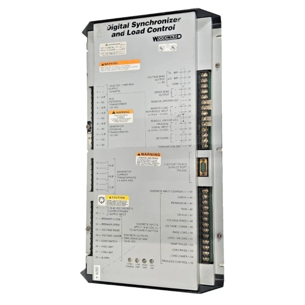
Description
Hard Numbers: Technical Specifications
(Note: The following specifications are compiled from typical 9905-973 operational parameters. Please consult the official Woodward documentation for exact project engineering.)
- Part Number: 9905-973
- Relay Channels: 8 Independent SPDT (Form C) relays
- Contact Rating: 5 A @ 240 V AC / 10 A @ 120 V AC (Resistive Load)
- Input Voltage Rating: 18–32 V DC (24V DC nominal)
- Power Consumption: 14 W typical
- Network Compatibility: Woodward LinkNet™
- Maximum Nodes per Bus: 64
- Network Isolation: 1000 Vrms (port-to-port)
- Communication Speed: 375 kbps (LinkNet™ baud rate)
- Environmental Operating Temp: 0°C to +70°C (32°F to 158°F)
- Dimensions (W x D x H): 8.75″ x 14.625″ x 5.375″ (222 mm x 371 mm x 137 mm)
- Weight: 9.11 lbs (4.13 kg) approx.
Woodward 9905-797
The Real-World Problem It Solves
In a modern power plant or offshore platform, the main turbine controller (like a Woodward 505E or Micronet) makes high-speed decisions in the “digital realm” (low-voltage DC signals). However, the physical equipment it needs to control—such as a massive fuel shut-off solenoid, a 240V AC lube oil pump, or a high-decibel emergency alarm horn—operates in the “realm of heavy electrical current.”
The Woodward 9905-973 acts as the crucial bridge (or “digital-to-physical translator”) between these two worlds. Without a robust relay module like this, the delicate low-voltage logic signals from your main controller wouldn’t stand a chance against the electrical noise and current demands of heavy industrial machinery. The 9905-973 takes those fragile digital commands and uses its internal electromechanical relays to safely and reliably switch high-power AC/DC circuits on and off .
Where you’ll typically find it:
- Gas & Steam Turbine Panels: Energizing critical shutdown solenoids and controlling gland steam valves .
- Generator Control Switchgear: Switching 240V AC annunciator alarms or controlling the closing coils of large generator breakers .
- Compressor Stations: Managing the start/stop sequences of large auxiliary motors (like cooling fans or oil pumps) based on the main compressor’s status .
Hardware Architecture & Under-the-Hood Logic
Unlike solid-state (transistor) outputs which can sometimes struggle with inductive loads, the 9905-973 uses time-tested electromechanical relays for robust power switching.
- LinkNet™ Communication Interface: The module connects to the main control network via a shielded twisted-pair cable. It listens for specific digital commands (bits) addressed to its unique node ID from the main turbine or engine controller .
- Optical Isolation: To protect the sensitive network communication chips from electrical noise (EMI/RFI) generated when switching heavy loads, the 9905-973 employs optical isolators (optocouplers) between the network side and the relay driver circuits .
- Relay Driver & Coils: When the LinkNet™ processor decodes a valid “Close Relay 1” command, it sends a 24V DC signal to the corresponding relay driver circuit. This energizes the coil of the electromechanical relay .
- SPDT Power Switching: Each of the 8 relays features a Single Pole, Double Throw (SPDT) configuration. When the coil is energized, it physically moves a metal armature that bridges the common (COM) terminal to the Normally Open (NO) terminal, completing the high-power circuit (e.g., turning on a 120V AC pump motor) .
- Built-in Diagnostics: The module constantly monitors the health of its own power supply and network communication. If it loses connection to the main controller or detects an internal fault, a dedicated “Fault” LED on the front panel will illuminate, alerting field technicians to the issue .
Woodward 9905-797
Field Service Pitfalls: What Rookies Get Wrong
Inductive Voltage Spikes (The “Ghost” Reset)
When switching inductive loads (like solenoid valves, motor windings, or magnetic contactors), rookies often forget to install external surge suppression.
- The Glitch: When the relay opens to turn off an inductive load, the collapsing magnetic field generates a massive reverse voltage spike (back-EMF). This spike travels back through the wiring and can couple into the 24V DC power supply or the LinkNet™ communication lines. This induces a “voltage glitch” that can cause the 9905-973 to reset itself or, worse, corrupt the LinkNet™ data packets, causing other modules on the bus to malfunction .
- Field Rule: Always install an RC snubber circuit or a diode (for DC loads) / MOV (for AC loads) directly across the coil of any inductive device being switched by the 9905-973. This safely absorbs the voltage spike at the source.
Exceeding Contact Ratings (Welded Contacts)
Rookies often look at the 10A @ 120V AC rating and assume it means the relay can safely switch anyload up to 10 Amps.
- The Danger: The 10A rating strictly applies to resistive loads (like a simple heating element or an incandescent light bulb). If you try to switch a highly inductive motor load (like a small pump) that draws 8-10 Amps running current, the initial inrush currentat startup could be 50-60 Amps. This will instantly arc across the relay contacts, welding them together in the closed position . Now, your lube oil pump won’t turn off, even during a turbine emergency stop.
- Field Rule: Derate the contacts heavily for inductive loads. As a rule of thumb, divide the resistive rating by 5 when switching inductive loads. If you need to switch a 10A motor, use an intermediate “pilot duty” contactor rated for 10A, and use the 9905-973 relay to switch the contactor’scoil instead.
Floating Grounds & Improper Shielding
The LinkNet™ network relies on a very specific electrical environment to maintain data integrity at 375 kbps.
- The Consequence: If the 24V DC power supply feeding the 9905-973 is not properly grounded, or if the cable shield for the LinkNet™ network is grounded at both ends (creating a ground loop), electrical noise from the nearby high-power AC wiring will be induced into the communication lines. The 9905-973 will lose communication with the main controller, causing all 8 relays to drop out simultaneously (failsafe state), which can lead to an unexpected turbine trip .
- Field Rule: Ensure the 24V DC power supply has a solid earth ground. Ground the LinkNet™ cable shield at the main controller end only. Keep the 9905-973’s communication cables routed strictly away from high-voltage AC wiring (maintain at least 6-12 inches of separation).
Commercial Availability & Pricing Note
Please note: The listed price is for reference only and is not binding. Final pricing and terms are subject to negotiation based on current market conditions and availability.


