
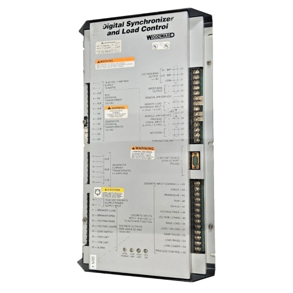
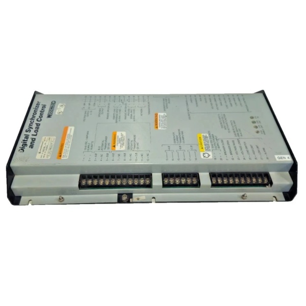
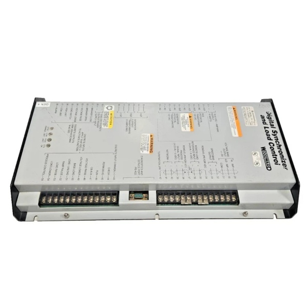
Description
Hard Numbers: Technical Specifications
(Note: The following specifications are compiled from typical 9905-972 operational parameters. Please consult the official Woodward documentation for exact project engineering.)
- Part Number: 9905-972
- Output Channels: 6 Independent Analog Outputs
- Output Range: 4–20 mA DC (Capable of driving 0–20 mA)
- Power Supply Input: 18–32 VDC (24V DC nominal)
- Power Consumption: Approx. 6.0 W at 24 VDC
- Communication Protocol: LinkNet™ I/O network interface
- Isolation Protection: Channel-to-channel and channel-to-ground isolation
- Communication Speed: 375 kbps (LinkNet™ baud rate)
- Maximum Nodes per Bus: 64
- Environmental Operating Temp: –40°C to +55°C (–40°F to +131°F)
- Hazardous Location Certification: Class I, Division 2, Groups A, B, C, D
- Mounting Method: DIN-Rail or Panel Mountable
- Enclosure Rating: Typically IP20 (dependent on cabinet installation)
- Physical Dimensions: 120 mm × 80 mm × 25 mm (approx. 4.7″ × 3.1″ × 1.0″)
- Weight: Approx. 0.59 kg (1.30 lbs)
Woodward 9905-797
The Real-World Problem It Solves
In a modern power generation facility or offshore platform, the main turbine controller (like a Woodward 505E or Micronet) operates purely in the digital realm, making high-speed decisions in millivolts and logic bits. However, the physical equipment it needs to command—such as fuel control valves, inlet guide vanes, or distillation column regulators—often relies on legacy analog electronics that require a precise 4-20mA current loop to operate .
The Woodward 9905-972 acts as the crucial “digital-to-analog bridge” in the LinkNet™ distributed I/O system. Without a robust module like this, the delicate low-voltage digital signals from your main controller would be drowned out by the intense electrical noise (EMI/RFI) generated by nearby 4160V motor cables and heavy inductive loads. The 9905-972 takes those fragile digital commands, converts them into isolated, noise-free 4-20mA analog currents, and drives industrial actuators with rock-solid precision, ensuring your turbine or process loop responds exactly as intended .
Where you’ll typically find it:
- Turbine Control Panels: Sending 4-20mA signals to electro-hydraulic converters (EHC) for steam turbine valve positioning .
- Gas Compressor Stations: Modulating fuel gas control valves to maintain precise speed and load sharing across multiple units .
- Distributed Control Systems (DCS): Providing isolated analog outputs from a central LinkNet™ network to remote field devices in hazardous (Class I Div 2) areas .
Hardware Architecture & Under-the-Hood Logic
Unlike a simple digital-to-analog converter (DAC) that merely drops voltage across a resistor, the 9905-972 is a highly engineered, industrial-grade current source. (Note: While predominantly an analog output module, certain legacy configurations may utilize 9905-972 variants as Peak 150 series steam turbine governors featuring AC/DC power inputs and Modbus communication capabilities .)
- LinkNet™ Communication Interface: The module connects to the main control network via a shielded twisted-pair cable. It continuously listens for specific digital data packets addressed to its unique node ID from the main turbine or engine controller .
- Optical Isolation & Signal Processing: To protect the sensitive network communication chips from electrical noise, the 9905-972 employs optical isolators (optocouplers) between the LinkNet™ processor and the DAC circuitry. The onboard microcontroller receives the digital command (e.g., “set output 1 to 50%”), processes it, and feeds it to a high-resolution DAC .
- Precision Current Amplification: The DAC generates a low-current analog voltage, which is then fed into a precision operational amplifier configured as a voltage-to-current (V-I) converter. This circuitry actively drives the output transistors to force exactly 4mA to 20mA of current through the external field wiring, regardless of the resistance in the loop (up to the compliance voltage limit) .
- Fault Detection & Diagnostics: The module constantly monitors the voltage across its output terminals. If it detects an open circuit (broken wire) or a short circuit in the field loop, it immediately flags a fault on the LinkNet™ network and illuminates a local diagnostic LED, alerting maintenance to a potential loss of control .
Woodward 9905-797
Field Service Pitfalls: What Rookies Get Wrong
The “Missing Common” Loop (No 4mA Baseline)
When wiring a 4-20mA analog output, rookies often focus entirely on the positive leg and forget how the current loop actually works.
- The Glitch: The 9905-972 sources the current, but if the rookie forgets to tie the analog common (A_COM) or the negative (-) terminal of the output channel to the DC power supply ground (or the DCS input card’s common), the current has no return path. The result? The output reads 0mA, and the control valve drifts to its fail-safe position (usually closed), causing the turbine to trip on “Loss of Valve Position Feedback” .
- Field Rule: Always trace the 4-20mA loop. Use a multimeter to confirm you have a solid, low-resistance path from the 9905-972’s output terminal, through the field device (actuator), and all the way back to the module’s common terminal.
Exceeding Compliance Voltage (The “Stuck” at 20mA Error)
Every analog output module has a “compliance voltage”—the maximum voltage it can generate to force current through a circuit. Rookies often overlook the resistance of long field cables.
- The Consequence: If you have a 9905-972 trying to push 20mA through a mile of small-gauge wire to a distant control valve, the total loop resistance might be 1200 ohms. To push 20mA through 1200 ohms, Ohm’s Law (V=IR) dictates you need 24 Volts. If the 9905-972’s compliance voltage is capped at 18V, it physically cannot drive 20mA. The output will max out (saturate) at, say, 15mA. The actuator will never reach its full open position, leading to chronic underperformance or “hunting” as the controller tries desperately to push the valve open .
- Field Rule: Calculate your worst-case loop resistance beforecommissioning. (Resistance = Wire Length × Wire Resistance per foot + Device Internal Resistance). If the required driving voltage exceeds 18-24V, you must use a larger gauge wire or install a remote booster amplifier.
Improper Grounding in Class I Div 2 Areas
The 9905-972 is certified for Class I, Division 2 hazardous locations, meaning it can operate in areas where flammable gases might occasionally be present.
- The Danger: Rookies often create “ground loops” by grounding the 24VDC power supply at the panel, and then separately grounding the DCS input card at the other end of the 4-20mA loop. This causes stray currents to flow through the ground path, interfering with the precise 4-20mA signal. In a Div 2 area, this signal jitter can cause a control valve to oscillate minutely, leading to premature valve seat wear and inaccurate process control .
- Field Rule: In Div 2 analog loops, ground the DC power supply at exactly one point (usually the power source). Ensure all shields on the twisted-pair cables are grounded at this single point only. Never let the analog signal common (A_COM) touch earth ground anywhere else in the loop.
Commercial Availability & Pricing Note
Please note: The listed price is for reference only and is not binding. Final pricing and terms are subject to negotiation based on current market conditions and availability.


