
Description
Hard-Numbers: Technical Specifications
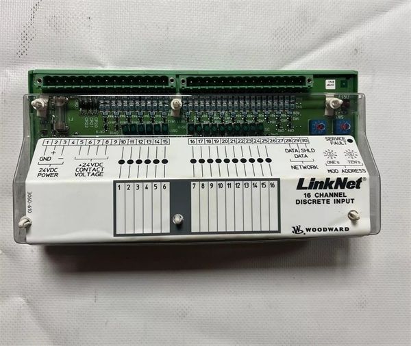
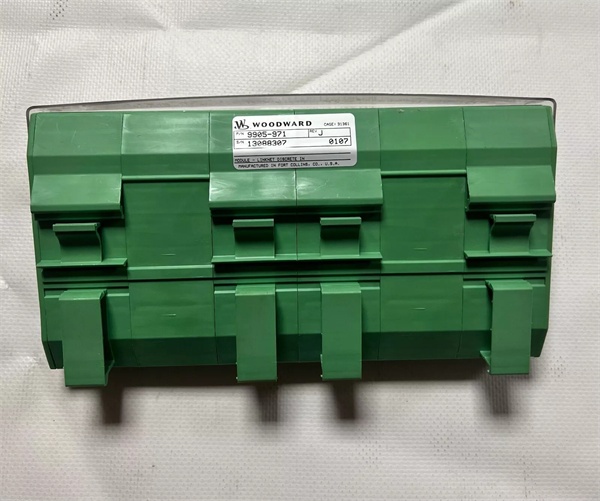
- Part Number: 9905-971
- Input Channels: 16 Discrete (Dry Contact or 24VDC sinking/sourcing)
- Communication Protocol: LinkNet / CAN 2.0B
- Power Supply: 24 VDC Nominal (Operating range typically 18-36 VDC)
- Isolation Voltage: 1500 VDC (Between field inputs and logic/ground)
- Bus Baud Rate: 125 kbps to 1 Mbps (Configurable)
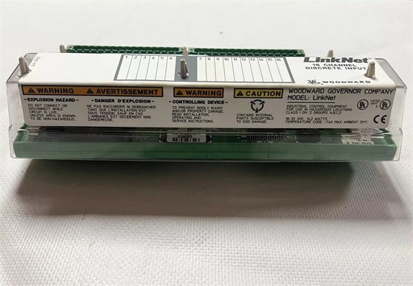
- Operating Temperature: -40°C to +70°C
- Mounting Style: DIN Rail Mount
- Environmental Rating: IP20 (Chassis), IP54 (with proper cabinet)
9905-971
The Real-World Problem It Solves
Running 16 individual wires from a remote emergency shutdown (ESD) valve back to the main control panel wastes copper, adds unnecessary terminations, and introduces electromagnetic noise into sensitive analog circuits. The 9905-971 acts as a rugged remote I/O drop, converting 16 local dry-contact signals into digital data packets and shooting them back to the main MicroNet processor over a single twisted-pair LinkNet bus.
Where you’ll typically find it:
- Mounted in a local junction box near the gas fuel skid of a Frame 5 turbine, gathering ESD pushbutton and solenoid valve limit switch statuses.
- Installed inside the auxiliary relay panel of a diesel generator set, monitoring circuit breaker positions and protective relay contacts.
- Used as a distributed input expander in power plants where running long multi-core cables is impractical due to existing conduit congestion.
It shrinks a bundle of 16 wires down to one bus cable.
Hardware Architecture & Under-the-Hood Logic
This module is a slave device on the LinkNet (CAN-based) network. It offloads the burden of scanning discrete inputs from the main CPU, freeing up the processor for high-speed closed-loop control like speed governing or synchronization.
- Signal Conditioning: Each of the 16 channels uses an opto-isolator to detect 24VDC or dry contact closures. This provides 1500VDC of galvanic isolation, protecting the internal logic from field-side voltage spikes or ground loops.
- Debounce & Latching: The onboard microcontroller applies hardware-level debouncing to filter out mechanical chatter from relays or switches. It then latches the state changes.
- Event Packet Generation: Instead of waiting for a poll request, the module generates a LinkNet broadcast packet whenever an input changes state. This ensures the main controller sees the event almost instantaneously (sub-millisecond resolution).
- Bus Transmission: The data packet is pushed onto the CAN 2.0B bus, prioritized by importance, and transmitted to the master MicroNet CPU or a DSLC/505 governor.
Field Service Pitfalls: What Rookies Get Wrong
Missing/Bad Bus Termination Leading to “Ghost” Trips
Inexperienced techs often daisy-chain the LinkNet bus from the CPU to the 9905-971 and walk away, forgetting that CAN-based networks absolutely require proper termination resistors at both physical ends of the cable run. Without the 120-ohm terminators, signal reflections bounce back down the line, causing random communication drops or spurious input bit flips.
- Field Rule: Grab a multimeter and measure the resistance across the CAN High and CAN Low terminals at the furthest device. You should read exactly 60 ohms (two 120-ohm resistors in parallel). If you read 120 ohms, your terminators aren’t configured correctly. Fix the wiring before commissioning the logic.
Incorrectly Wired Sinking/Sourcing Inputs Causing “Always Active” Status
A common rookie mistake is assuming all 24VDC inputs are created equal. They wire a normally-open (NO) dry contact directly to the 9905-971 terminal without supplying a 24VDC source or ground reference. The input floats, picking up induced voltage from nearby contactors, making the CPU think the ESD button is constantly pressed.
- Field Rule: Check your sinking vs. sourcing requirements. For dry contacts, you usually need to jumper the common (COM) terminal to either +24VDC or 0VDC (depending on the module’s internal architecture) so the input has a definitive resting state. Never leave a discrete input floating.
Mounting the Module in a High-Vibration Area Without Strain Relief
Field techs often bolt the DIN rail directly to the side of a compressor skid or gearbox to save space, right next to high-amplitude vibration sources. Over time, the micro-cracks in the solder joints of the 1206-size surface mount components propagate, leading to intermittent bus communication failures or complete module death.
- Field Rule: Mount the 9905-971 in a properly grounded metal enclosure that isolates it from structural vibrations. Use shielded twisted pair (STP) for the LinkNet cable and clamp it down with strain reliefs. Vibration is the silent killer of cheap circuit boards.
9905-971
Commercial Availability & Pricing Note
Please note: The listed price is for reference only and is not binding. Final pricing and terms are subject to negotiation based on current market conditions and availability.


