
Description
Hard-Numbers: Technical Specifications
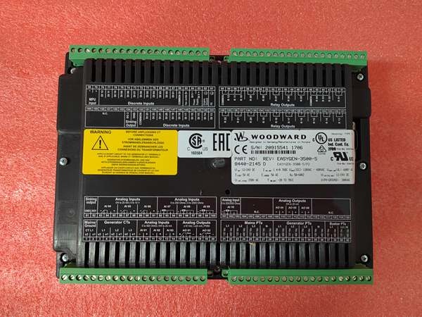
- Part Number: 9905-392
- Power Supply: 20 to 40 VDC (Nominal 24VDC), 15W min power requirement
- Actuator Output: 0–200 mA (Driving a proportional electric actuator)
- Speed Sensor Input: Magnetic pickup (MPU) compatible
- Speed Ranges: Selectable 500-1500 Hz, 1000-3000 Hz, 2000-6000 Hz, or 4000-12000 Hz
- Load Sharing Input: 0–3 Vdc (into 25 kΩ impedance in isochronous mode)
- Output to Speed Control: +0.5 to +4.5 Vdc analog, or ±3 Vdc analog
- Operating Temperature: -40°C to +70°C
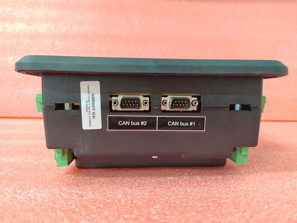
- Communications: Compatible with Woodward SPM-A/SPM-D Synchronizers
The Real-World Problem It Solves
Trying to parallel two diesel generators with mismatched mechanical governors is an exercise in frustration. The 9905-392 eliminates the tedious manual tweaking and “hunting” by providing precise, closed-loop speed control and load sharing. It reads the generator’s frequency and real-time kilowatt load, then automatically adjusts the engine throttle to maintain perfect synchronization with the bus.
Where you’ll typically find it:
- Mounted in the control cabinet of a standby diesel generator set, managing the Woodward actuator on the fuel rack.
- Installed in pump stations or compressor drives (especially with electric motors or turbines) where precise speed control is mandatory.
- Retrofitted into older generator panels to replace obsolete, drifting analog governor controls, bringing the system up to modern paralleling standards.
It keeps the Hertz steady and splits the load evenly between machines.
Hardware Architecture & Under-the-Hood Logic
The 9905-392 is a self-contained analog computing module. Despite its age, it remains highly effective because it processes real-time feedback instantaneously without the overhead of digital scan cycles.
- Speed Sensing: The module takes the frequency input from a magnetic pickup (MPU) on the crankshaft and converts it into a stable DC voltage proportional to the engine’s RPM.
- Error Amplification: It compares the actual speed voltage to the desired speed setpoint (from a potentiometer or external signal). The difference creates a “speed error” signal.
- Load Compensation: In isochronous mode, it takes the 0-3VDC load signal from a current transformer (CT) and potential transformer (PT) network. It algebraically adds this to the speed error to determine the exact throttle position needed to maintain the target RPM under changing loads.
- Actuator Drive: The summed signal drives a high-impedance amplifier stage, outputting 0-200mA to the Woodward proportional actuator, which physically pushes the fuel control linkage.
Field Service Pitfalls: What Rookies Get Wrong
Mismatched Speed Range DIP Switches Causing Runaway
A classic rookie mistake is installing the unit, applying power, and watching the engine immediately race to catastrophic overspeed because the DIP switches for the MPU frequency range were set incorrectly. If the switches are set for 500-1500 Hz but the engine’s MPU puts out 2000 Hz at idle, the module thinks the engine is stalling and floors the throttle.
- Field Rule: Calculate your MPU’s frequency at cranking speed and at rated speed beforeyou set the DIP switches. Use a handheld frequency meter on the MPU leads while cranking to verify your math. Never guess.
Improper CT/PT Phasing Resulting in “Negative” Load Sharing
When commissioning a paralleling system, a junior tech might wire the load sharing CTs and PTs with slightly reversed polarity. The 9905-392 will happily accept the signal, but instead of sharing the load, it will do the exact opposite—when you manually raise the load on one generator, the other generator will dump its load to zero.
- Field Rule: During initial startup on an infinite bus, put the control in “Droop” mode first. Manually raise the generator’s load. If the speed increasesas load increases, your phasing is reversed. Swap the secondary wires on your CTs.
Installing the Actuator Linkage with Mechanical Advantage Issues
Techs often bolt the Woodward actuator to the engine fuel linkage without checking the physical leverage. If the actuator’s linear travel doesn’t perfectly match the fuel rack’s full stroke, the module’s internal feedback loop will clip, resulting in terrible speed droop or an inability to reach full governed speed.
- Field Rule: Calibrate the actuator stroke mechanically beforeclosing the loop. With the engine off, command 0% and 100% fuel from the 9905-392 and verify the physical fuel rack hits its mechanical stops exactly at those commands. Adjust the clevis pins and lever arms until the mechanical and electrical ranges are 1:1.
8440-2189
Commercial Availability & Pricing Note
Please note: The listed price is for reference only and is not binding. Final pricing and terms are subject to negotiation based on current market conditions and availability.


