
Description
Key Technical Specifications
-
Model Number: 9905-377
-
Manufacturer: Woodward
-
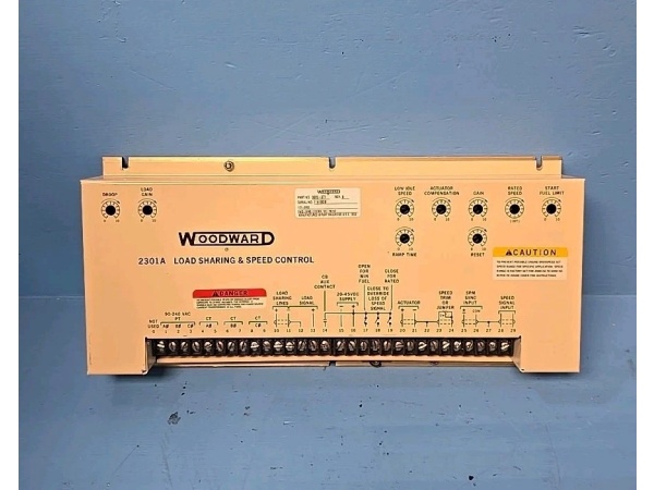
Supply Voltage: 20-40 VDC (low-volt); 88-131 VAC or 90-150 VDC (high-volt) selectable
-
Actuator Output: 0-200 mA into 40 Ω max, reverse-acting (200 mA = idle, 0 mA = full speed)
-
Speed Reference Input: 1-5 VDC (or 4-20 mA via 250 Ω jumper)
-
MPU Input: 1-30 V p-p, 1 kHz–25 kHz, 0.010–0.040 in. air-gap
-
Load Sharing Input: 0-6 VDC from 5 A CT secondary, gain trim on board
-
Droop Range: 0-10 % via 20-turn pot; isochronous when pot fully CCW
-
Operating Temperature: –40 °C to +85 °C
-
Power Consumption: 8 W typical, 15 W max
-
Isolation: 500 V input-to-output, opto-coupled speed share line
-
Mounting: 8.5″ × 2″ Euro-card, slides in 2301A chassis or DIN clips

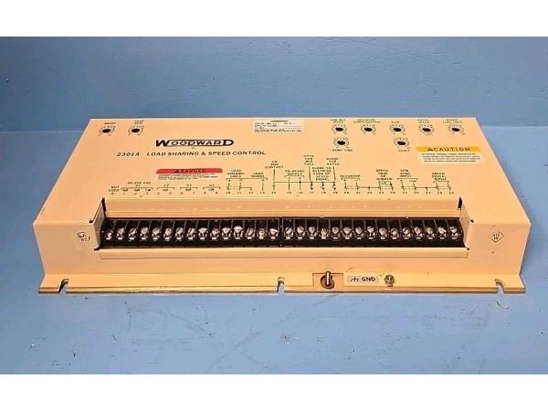
WOODWARD 9905-377
Field Application & Problem Solved
Steam-turbine throttle valves are engineered fail-closed—lose control signal and the valve must slam shut under spring force to prevent overspeed. The 9905-377 is Woodward’s reverse-acting solution: 200 mA holds the valve at minimum position (idle), 0 mA lets it spring wide open to maximum speed. I deploy this on 10 MW extraction units in paper mills and chemical plants where the throttle is air-to-open, spring-to-close. The card sits in the 2301A chassis, takes MPU pulses from the gearbox, and drives a Woodward TG-17 or UG-8 actuator. When the unit trips, cable breaks, or power fails, current collapses to zero and the valve closes—no runaway, no overspeed event. Commissioning is backwards from forward-acting cards: at 0 % speed demand you want 200 mA (valve closed), at 100 % you want 0 mA (valve open). Get the direction wrong and the turbine screams to 120 % speed on the first start attempt.
Steam-turbine throttle valves are engineered fail-closed—lose control signal and the valve must slam shut under spring force to prevent overspeed. The 9905-377 is Woodward’s reverse-acting solution: 200 mA holds the valve at minimum position (idle), 0 mA lets it spring wide open to maximum speed. I deploy this on 10 MW extraction units in paper mills and chemical plants where the throttle is air-to-open, spring-to-close. The card sits in the 2301A chassis, takes MPU pulses from the gearbox, and drives a Woodward TG-17 or UG-8 actuator. When the unit trips, cable breaks, or power fails, current collapses to zero and the valve closes—no runaway, no overspeed event. Commissioning is backwards from forward-acting cards: at 0 % speed demand you want 200 mA (valve closed), at 100 % you want 0 mA (valve open). Get the direction wrong and the turbine screams to 120 % speed on the first start attempt.
Installation & Maintenance Pitfalls (Expert Tips)
Verify Acting Direction Before Spinning the Shaft
Bump speed reference to 10 %—actuator current should drop from 200 mA toward 180 mA. If it climbs, you have a forward-acting card (9905-004, 148, or 726) in the slot. Swap it immediately or you’ll overspeed on start.
Bump speed reference to 10 %—actuator current should drop from 200 mA toward 180 mA. If it climbs, you have a forward-acting card (9905-004, 148, or 726) in the slot. Swap it immediately or you’ll overspeed on start.
Set Null with Valve Physically Closed
At 0 % demand, dial the null pot until you read exactly 200 mA. Any less and the valve leaks steam at idle; any more and you lose headroom to close fully during a trip. I use a 0.1 Ω shunt and a calibrated DVM—clamp meters lie at this current level.
At 0 % demand, dial the null pot until you read exactly 200 mA. Any less and the valve leaks steam at idle; any more and you lose headroom to close fully during a trip. I use a 0.1 Ω shunt and a calibrated DVM—clamp meters lie at this current level.
MPU Phase Sequence is Critical
Reverse the MPU A/B wires and the card thinks the shaft is spinning backwards—valve drives full open when you ask for stop. Check with a scope: Channel A should lead B by 90° when viewed from the governor end. Mark the wires with heat-shrink before you close the terminal strip.
Reverse the MPU A/B wires and the card thinks the shaft is spinning backwards—valve drives full open when you ask for stop. Check with a scope: Channel A should lead B by 90° when viewed from the governor end. Mark the wires with heat-shrink before you close the terminal strip.
Lock the Droop Pot After Setting
Vibration walks the 20-turn pot in 500-1000 hours. After setting 4 % droop, secure the shaft with nail polish or non-hardening thread-lock. I’ve seen pots drift to 10 % droop and plants shed 400 kW base-load before operators traced it to the governor.
Vibration walks the 20-turn pot in 500-1000 hours. After setting 4 % droop, secure the shaft with nail polish or non-hardening thread-lock. I’ve seen pots drift to 10 % droop and plants shed 400 kW base-load before operators traced it to the governor.
Don’t Parallel Actuators on One Card
Two 40 Ω coils in parallel present 20 Ω to the current source. The card hits its 220 mA limit early and speed hunts ±5 Hz as the loop saturates. Use separate 9905-377 cards or add 20 Ω series resistors to each leg.
Two 40 Ω coils in parallel present 20 Ω to the current source. The card hits its 220 mA limit early and speed hunts ±5 Hz as the loop saturates. Use separate 9905-377 cards or add 20 Ω series resistors to each leg.
WOODWARD 9905-377
Technical Deep Dive & Overview
The 9905-377 is an analog reverse-acting speed/load control built on a four-layer Euro-card. A magnetic pickup zero-cross detector feeds a CD4046 phase-locked loop; the loop compares shaft frequency to an internal 60 Hz temperature-compensated crystal reference. The resulting error drives a PNP current source that outputs 200-0 mA (inverted from the 9905-726). Load-sharing current from a 5 A generator CT converts to 0-6 V through a precision burden resistor, sums at the PID summing junction, and applies droop via the 20-turn front-panel potentiometer. An LM336 5 V reference feeds the local speed-set pot; external 1-5 V or 4-20 mA commands can override via DIP jumper.
The 9905-377 is an analog reverse-acting speed/load control built on a four-layer Euro-card. A magnetic pickup zero-cross detector feeds a CD4046 phase-locked loop; the loop compares shaft frequency to an internal 60 Hz temperature-compensated crystal reference. The resulting error drives a PNP current source that outputs 200-0 mA (inverted from the 9905-726). Load-sharing current from a 5 A generator CT converts to 0-6 V through a precision burden resistor, sums at the PID summing junction, and applies droop via the 20-turn front-panel potentiometer. An LM336 5 V reference feeds the local speed-set pot; external 1-5 V or 4-20 mA commands can override via DIP jumper.
The output stage is a discrete PNP current source with foldback limiting—intentionally designed to fail to zero mA on loss of 24 V supply, ensuring the steam valve closes under spring force. The card includes 500 V opto-isolation on the speed-share line to prevent ground loops between paralleled units. No microprocessor, no firmware, no boot time—pure analog control that settles in 50 ms and survives 500 V transients, reverse battery, and 150 °F panel temperatures. The 377 revision adds thicker conformal coating and replaces early vintage carbon-comp resistors with metal-film for long-term stability in H₂S environments.


