
Description
Key Technical Specifications
-
Model Number: 9905-367
-
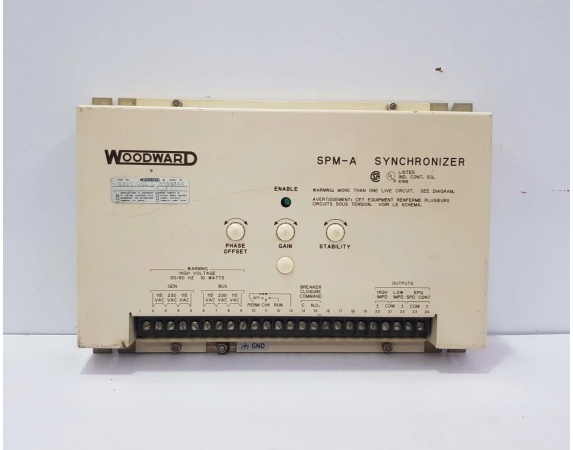
Manufacturer: Woodward Inc.
-
Product Family: DSLC (Digital Synchronizer and Load Control) – Master Unit
-
Input Voltage: 115 VAC or 230 VAC (switch-selectable), 50/60 Hz
-
Power Consumption: 10 VA maximum (typical for DSLC series)
-
Synchronization Method: Digital phase-locked loop with microprocessor control for 3-phase systems
-
Phase Angle Matching: ±5° to ±20° (adjustable via front panel or software)
-
Voltage Matching: Within 1% to 5% of bus voltage (programmable)
-
Frequency Matching: Biases offline generator speed to match bus frequency
-
Output Options:
-
Speed bias output to governor (raise/lower)
-
Voltage bias output to AVR (raise/lower)
-
Breaker close relay contact (dry contact, typically 5A)
-
Load sharing line interface (0-6 Vdc analog)
-
-
Load Control Integration: Built-in load sharing and load ramp functions
-
Operating Temperature: -40°C to +70°C (-40°F to +158°F)
-
Storage Temperature: -55°C to +85°C (-67°F to +185°F)
-
Relative Humidity: 5% to 95% non-condensing
-
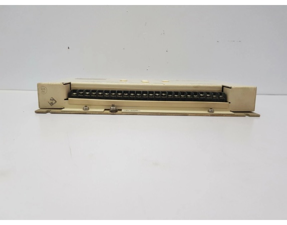
Mounting: Panel-mounted in control cabinet
-
Dimensions: Approximately 200 mm × 120 mm × 50 mm (typical DSLC form factor)
-
Weight: 0.6 kg (1.3 lb)
-
Front Panel Interface: LED indicators for sync status, alarms, and mode selection
-
Compatibility: 2301A, 2301E, EPG, and other Woodward governor systems
-
Special Feature: Master control capability for coordinating multiple DSLC units

Woodward 9905-001-L
Field Application & Problem Solved
In the field, the biggest challenge with multi-unit paralleling isn’t just synchronizing one generator—it’s coordinating multiple units to come online in sequence without fighting each other or creating system disturbances. The 9905-367 solves this as a Master DSLC, acting as the orchestra conductor for your paralleling system. While standard DSLC units (like the 9905-373) handle individual generator synchronization, the 9905-367 provides system-level coordination.
You will typically find this module in larger power plants with three or more generators, marine switchboards with complex power management systems, and industrial facilities requiring staged paralleling sequences. It’s designed to work as the master controller in a multi-DSLC architecture, where individual DSLC units (slaves) report to the 9905-367 for coordinated load sharing and synchronization timing. This prevents the “race condition” where multiple generators try to synchronize simultaneously, causing chaos on the load sharing lines.
Its core value is providing deterministic, sequenced paralleling in complex systems. The master unit calculates optimal synchronization timing for each generator based on system load, available capacity, and priority settings. It manages the load sharing bus, ensuring that as each unit comes online, it picks up its proportional share without disturbing the already-running units. The 3-phase monitoring capability provides redundant voltage sensing—if one phase drops out or goes abnormal, the master can detect it and prevent paralleling into a faulted bus. This is critical in marine applications where single-phasing events can destroy rotating equipment.
Installation & Maintenance Pitfalls (Expert Tips)
Master/Slave Configuration is Critical
The most common field mistake with the 9905-367 is improper addressing of slave units. Each DSLC in the system must have a unique address, and the 9905-367 must be configured as the master. If two units are both set to master, you’ll see conflicting commands on the load sharing lines—generators hunting, breakers chattering, and potential damage to the synchronization circuits. Use the front-panel DIP switches or software configuration to set addresses before power-up. Document your addressing scheme on the cabinet door for future technicians.
3-Phase PT Connections Must Be Phased Identically
The 9905-367 monitors all three phases for synchronization. If your generator PTs are wired with different phase rotation than the bus PTs—or if one phase is swapped—the master will see a constant phase error and refuse to synchronize, or worse, command synchronization at the wrong instant. Always verify phase rotation with a phase sequence meter during commissioning. Mark the PT secondary leads clearly (A-B-C on both generator and bus sides). I’ve seen installations where maintenance crews swapped B and C phases during routine PT replacement, resulting in immediate breaker damage when the master commanded closure 120 degrees out of phase.
Load Sharing Line Termination in Multi-Unit Systems
With multiple DSLC units on the same load sharing bus, impedance matching becomes critical. The 9905-367 as master typically drives the bus, while slave units receive. If the load sharing lines are not terminated properly (usually 100-ohm termination resistors at the physical ends of the bus), you’ll get signal reflections causing erratic load sharing. This manifests as generators oscillating in load—unit 1 surging while unit 2 sags, then reversing. Install termination resistors at the furthest physical ends of the load sharing wiring, not at each unit.
Master Override Timing Can Confuse Operators
The 9905-367 has master override capability—it can force synchronization or load sharing decisions that override local DSLC settings. Operators unfamiliar with this feature may think a local unit is malfunctioning when it’s actually following master commands. During commissioning, clearly label which units are master-controlled and which operate independently. Train your operators that the master unit’s front panel indicators show system status, not just local status. If the master shows “Sync Inhibit,” all units in the system are inhibited, regardless of their local indications.
Communication Wiring Between Master and Slaves
If your 9905-367 uses serial communication to coordinate with slave DSLC units (RS-485 or similar), this wiring is as critical as the power wiring. Shielded twisted pair is mandatory, with the shield grounded at the master end only. I’ve seen installations where communication errors caused the master to lose track of slave status, resulting in two generators synchronizing simultaneously. The master thought unit 2 was offline when it was actually running, and commanded a parallel into a live bus. Use proper termination resistors on the communication bus and verify data integrity with a protocol analyzer during commissioning.
Dead Bus Logic Requires Careful Setup
The 9905-367 handles dead bus closing—energizing a de-energized bus from the first available generator. This requires voltage sensing thresholds that distinguish between a truly dead bus and a weak or faulted bus. If your undervoltage pickup setting is too low, the master may close into a faulted bus with a high-impedance ground. If too high, it won’t recognize a legitimate dead bus condition. Set the dead bus voltage threshold at 15-20% of nominal, and always verify with intentional dead bus tests during commissioning.
Woodward 9905-001-L
Technical Deep Dive & Overview
The Woodward 9905-367 is a microprocessor-based Master Digital Synchronizer and Load Control from the DSLC series, representing Woodward’s digital evolution of paralleling technology with system-level coordination capabilities. It combines the functions of synchronization, load sharing, and system sequencing into a single digital platform, acting as the master controller in multi-generator power systems.
The module operates by sampling the voltage waveforms from both the bus and generator potential transformers at high speed across all three phases, then using digital signal processing algorithms to calculate phase angle, frequency difference, and voltage magnitude in real-time. Unlike standard DSLC units that operate independently, the 9905-367 coordinates multiple DSLC slave units through digital communication, managing the paralleling sequence to prevent simultaneous synchronization attempts.


