
Description
Key Technical Specifications
-
Model Number: 9905-111
-
Manufacturer: Woodward
-
Supply Voltage: 20-40 VDC (low-volt); 88-131 VAC or 90-150 VDC (high-volt) selectable
-
Actuator Output: 0-200 mA into 40 Ω max, forward-acting (0 mA = idle, 200 mA = full speed)
-
Speed Reference Input: 1-5 VDC (or 4-20 mA via 250 Ω jumper)
-
MPU Input: 1-30 V p-p, 1 kHz–25 kHz, 0.010–0.040 in. air-gap
-
Load Sharing Input: 0-6 VDC from 5 A CT secondary, gain trim on board
-
Droop Range: 0-10 % via 20-turn pot; isochronous when pot fully CCW
-
Operating Temperature: –40 °C to +85 °C
-
Power Consumption: 8 W typical, 15 W max
-
Isolation: 500 V input-to-output, opto-coupled speed share line
-
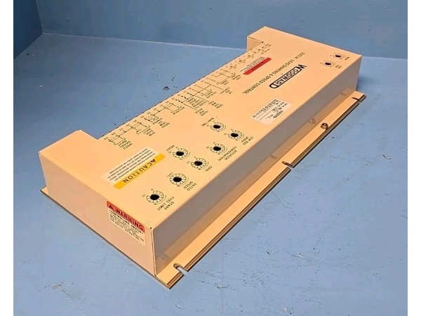
Mounting: 8.5″ × 2″ Euro-card, slides in 2301A chassis or DIN clips

WOODWARD 9905-377
Field Application & Problem Solved
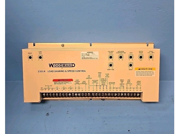
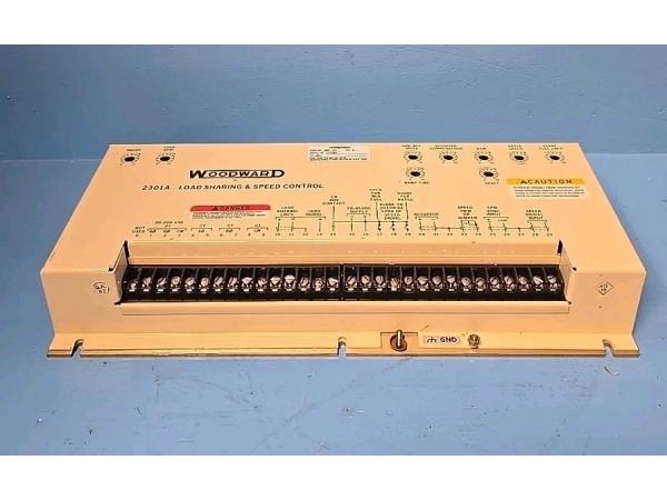
Small gas turbines and diesel gensets in industrial plants need precise speed control to maintain power quality and avoid tripping on frequency deviation. The 9905-111 is a forward-acting member of the 2301A family: 0 mA at idle, 200 mA at full speed, driving a Woodward PG-PL or TG-13 actuator on the fuel valve. I install these on 2-5 MW cogen units in manufacturing plants and 1-3 MW emergency power systems in hospitals where the turbine must parallel with the grid or run island mode during outages. Load-sharing input from a 5 A CT lets multiple units share load proportionally; the droop pot sets 4-5 % so the unit doesn’t fight the grid frequency. One card replaces the mechanical governor, droop linkage, and a rack of relays—simplifying maintenance and improving reliability. Commissioning is straightforward: set droop to 4 %, dial null at 0 mA, bump speed until the synchroscope stops drifting. The result is stable frequency, clean power, and no operator babysitting.
Small gas turbines and diesel gensets in industrial plants need precise speed control to maintain power quality and avoid tripping on frequency deviation. The 9905-111 is a forward-acting member of the 2301A family: 0 mA at idle, 200 mA at full speed, driving a Woodward PG-PL or TG-13 actuator on the fuel valve. I install these on 2-5 MW cogen units in manufacturing plants and 1-3 MW emergency power systems in hospitals where the turbine must parallel with the grid or run island mode during outages. Load-sharing input from a 5 A CT lets multiple units share load proportionally; the droop pot sets 4-5 % so the unit doesn’t fight the grid frequency. One card replaces the mechanical governor, droop linkage, and a rack of relays—simplifying maintenance and improving reliability. Commissioning is straightforward: set droop to 4 %, dial null at 0 mA, bump speed until the synchroscope stops drifting. The result is stable frequency, clean power, and no operator babysitting.
Installation & Maintenance Pitfalls (Expert Tips)
MPU Air-Gap is Critical
Gap over 0.040″ and the card loses the signal—valve snaps shut and you trip on underspeed. Gap under 0.010″ and the pickup grinds the gear teeth. I set 0.025″ cold, then verify hot; thermal growth closes the gap about 0.003″. Check it every outage—vibration loosens the bracket.
Gap over 0.040″ and the card loses the signal—valve snaps shut and you trip on underspeed. Gap under 0.010″ and the pickup grinds the gear teeth. I set 0.025″ cold, then verify hot; thermal growth closes the gap about 0.003″. Check it every outage—vibration loosens the bracket.
Droop Pot Drifts Under Vibration
The 20-turn pot loosens in 500-1000 hours of operation. After setting 4 % droop, lock the shaft with nail polish or non-hardening thread-lock. I’ve seen units drop 100 kW because the pot walked to 7 % droop, causing the plant to import power unexpectedly.
The 20-turn pot loosens in 500-1000 hours of operation. After setting 4 % droop, lock the shaft with nail polish or non-hardening thread-lock. I’ve seen units drop 100 kW because the pot walked to 7 % droop, causing the plant to import power unexpectedly.
Current Output Needs 40 Ω Exactly
Actuator coil is 38 Ω cold, 42 Ω hot—perfect match. Parallel two actuators and impedance drops to 20 Ω; the card current-limits at 220 mA and speed hunts ±5 Hz. Use separate cards or add 20 Ω series resistance. Measure the coil with a DVM at operating temperature—don’t trust the nameplate.
Actuator coil is 38 Ω cold, 42 Ω hot—perfect match. Parallel two actuators and impedance drops to 20 Ω; the card current-limits at 220 mA and speed hunts ±5 Hz. Use separate cards or add 20 Ω series resistance. Measure the coil with a DVM at operating temperature—don’t trust the nameplate.
Verify Speed Reference Polarity Before Start
Reverse the 1-5 V wires and the valve drives shut when you ask for 100 %. Bump demand to 10 %—actuator current should climb toward 20 mA. If it drops, swap wires at the terminal strip, not at the DCS, to keep the control loop intact. Label the wires before you start—saves troubleshooting time.
Reverse the 1-5 V wires and the valve drives shut when you ask for 100 %. Bump demand to 10 %—actuator current should climb toward 20 mA. If it drops, swap wires at the terminal strip, not at the DCS, to keep the control loop intact. Label the wires before you start—saves troubleshooting time.
Check Load Sharing Gain Before Paralleling
The gain trim pot sets how aggressively the unit responds to circulating current. Too high and the turbine hunts against the grid; too low and it won’t share load properly. Start at mid-range, parallel at 10 % load, then trim until kW splits evenly with other units. Mark the final position—it’s field-adjusted, not factory-set.
The gain trim pot sets how aggressively the unit responds to circulating current. Too high and the turbine hunts against the grid; too low and it won’t share load properly. Start at mid-range, parallel at 10 % load, then trim until kW splits evenly with other units. Mark the final position—it’s field-adjusted, not factory-set.
WOODWARD 9905-377
Technical Deep Dive & Overview
The 9905-111 is an analog forward-acting speed/load control on a four-layer Euro-card. A magnetic pickup zero-cross detector feeds a CD4046 phase-locked loop; the loop compares shaft frequency to an internal 60 Hz temperature-compensated crystal reference and generates a 0-200 mA error signal. Load-sharing current from a 5 A generator CT converts to 0-6 V through a precision burden resistor, sums at the PID summing junction, and applies droop via the 20-turn front-panel potentiometer. An LM336 5 V reference feeds the local speed-set pot; external 1-5 V or 4-20 mA commands can override via DIP jumper.
The 9905-111 is an analog forward-acting speed/load control on a four-layer Euro-card. A magnetic pickup zero-cross detector feeds a CD4046 phase-locked loop; the loop compares shaft frequency to an internal 60 Hz temperature-compensated crystal reference and generates a 0-200 mA error signal. Load-sharing current from a 5 A generator CT converts to 0-6 V through a precision burden resistor, sums at the PID summing junction, and applies droop via the 20-turn front-panel potentiometer. An LM336 5 V reference feeds the local speed-set pot; external 1-5 V or 4-20 mA commands can override via DIP jumper.
The output stage is a complementary NPN/PNP current source with foldback limiting—survives short circuits and reverse battery connection. The card includes 500 V opto-isolation on the speed-share line to prevent ground loops between paralleled units. No microprocessor, no firmware, no boot time—pure analog control that settles in 50 ms and survives 500 V transients, 150 °F panel temperatures, and years of vibration. The 111 revision uses metal-film resistors for long-term stability and standard acrylic conformal coating. For harsh environments with H₂S or salt air, look for the 111K revision with upgraded polyurethane coating and 105 °C rated capacitors.


