
Description
Key Technical Specifications
-
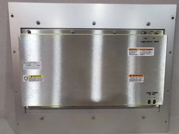
Model Number: 9905-068C
-
Manufacturer: Woodward
-
Sensing Voltage: 115 VAC or 230 VAC (jumper-selectable), 45-65 Hz
-
Power Supply: 18-32 VDC or 88-132 VAC (selectable)
-
Power Consumption: 15 W max
-
Phase Window: ±0.5° electrical (digital calculation)
-
Slip Frequency: 0.02-0.5 Hz programmable
-
Speed Bias Output: 0-10 VDC or 4-20 mA into 500 Ω
-
Load Control Output: 4-20 mA for import/export or base load
-
Breaker Control: 2× Form-C relays, 5 A @ 250 VAC/30 VDC
-
Communications: RS-485 Modbus RTU (optional), 9600-19200 baud
-
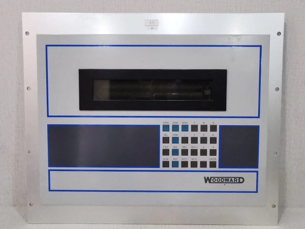
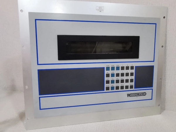
Display: 4-digit LED for frequency, phase angle, voltage differential
-
Operating Temperature: –20 °C to +60 °C
-
Mounting: 8.5″ × 4″ panel-mount chassis, DIN rail optional

WOODWARD 5453-203
Field Application & Problem Solved
Old analog synchroscopes work until they don’t—drift, calibration issues, and human error cause more breaker trips than actual faults. The 9905-068C is Woodward’s digital upgrade: a microprocessor watches generator and bus waveforms, calculates phase angle within half a degree, and closes the breaker at the exact zero-crossing. I install these on 5-20 MW cogen units in refineries and paper mills where they parallel multiple times daily with the utility. The built-in load control means it doesn’t just sync—it manages import/export setpoints via 4-20 mA to the 2301A or 505, holding a dead-band of ±10 kW so the utility never sees a swing. One box replaces the synchroscope, the import/export card (9905-092), and the manual load trim pot. Commissioning: set PT ratio, dial in your dead-band, and let it run—no more operator guessing games.
Old analog synchroscopes work until they don’t—drift, calibration issues, and human error cause more breaker trips than actual faults. The 9905-068C is Woodward’s digital upgrade: a microprocessor watches generator and bus waveforms, calculates phase angle within half a degree, and closes the breaker at the exact zero-crossing. I install these on 5-20 MW cogen units in refineries and paper mills where they parallel multiple times daily with the utility. The built-in load control means it doesn’t just sync—it manages import/export setpoints via 4-20 mA to the 2301A or 505, holding a dead-band of ±10 kW so the utility never sees a swing. One box replaces the synchroscope, the import/export card (9905-092), and the manual load trim pot. Commissioning: set PT ratio, dial in your dead-band, and let it run—no more operator guessing games.
Installation & Maintenance Pitfalls (Expert Tips)
Ground the Shield at One End Only—But Pick the Right End
The 9905-068C has enough digital noise immunity to survive most plants, but the PT cables are the weak link. I ground the shield at the card end, never at the switchgear—ground loops will give you ±2° phase jitter and the breaker will chatter instead of closing clean.
The 9905-068C has enough digital noise immunity to survive most plants, but the PT cables are the weak link. I ground the shield at the card end, never at the switchgear—ground loops will give you ±2° phase jitter and the breaker will chatter instead of closing clean.
Program the Slip Frequency Before You Apply Generator Voltage
Default is 0.1 Hz, which is fine for 4-pole machines. On a 3600 RPM gas turbine, 0.1 Hz is too sloppy—you’ll see 10° phase error at closure. Drop it to 0.02 Hz in the menu, but realize the sync check takes 30 seconds longer. Balance speed against accuracy for your application.
Default is 0.1 Hz, which is fine for 4-pole machines. On a 3600 RPM gas turbine, 0.1 Hz is too sloppy—you’ll see 10° phase error at closure. Drop it to 0.02 Hz in the menu, but realize the sync check takes 30 seconds longer. Balance speed against accuracy for your application.
The “C” Revision Has a Firmware Bug in Import Mode
Early 9905-068C units (serial numbers below C-45000) will hunt on import control if the utility frequency drifts >0.5 Hz. Flash to revision C.2 or later—Woodward has the hex file on their support site. If you can’t flash, add a 0.5 Hz dead-band in the 2301A to mask the oscillation.
Early 9905-068C units (serial numbers below C-45000) will hunt on import control if the utility frequency drifts >0.5 Hz. Flash to revision C.2 or later—Woodward has the hex file on their support site. If you can’t flash, add a 0.5 Hz dead-band in the 2301A to mask the oscillation.
Don’t Trust the LED Display for Phase Angle
It’s accurate to ±0.5°, but only updates every 100 ms. If your slip is 0.3 Hz, the real phase angle has moved 10.8° between updates. Use the analog speed bias output to verify the loop is actually tracking—scope it for a clean ramp, not steps.
It’s accurate to ±0.5°, but only updates every 100 ms. If your slip is 0.3 Hz, the real phase angle has moved 10.8° between updates. Use the analog speed bias output to verify the loop is actually tracking—scope it for a clean ramp, not steps.
Check the Relay Contact Rating—It’s Not 10 A
The Form-C outputs are rated 5 A resistive, 2 A inductive. I’ve seen techs drive a 5 A breaker coil directly; the contacts weld in six months. Interpose a 24 VDC ice-cube relay, or better yet, use the dry contacts to pull in a PLC input and let the PLC handle the heavy lifting.
The Form-C outputs are rated 5 A resistive, 2 A inductive. I’ve seen techs drive a 5 A breaker coil directly; the contacts weld in six months. Interpose a 24 VDC ice-cube relay, or better yet, use the dry contacts to pull in a PLC input and let the PLC handle the heavy lifting.
WOODWARD 5453-203
Technical Deep Dive & Overview
The 9905-068C is a 16-bit microprocessor-based synchronizer built around an Intel 80C196 microcontroller. Input transformers scale PT signals to 5 VAC; a 12-bit A/D samples both channels at 1 kHz, and firmware calculates zero-crossings, phase angle, and slip frequency using a 3-sample digital filter. The phase-locked loop updates every 10 ms, outputting a 0-10 VDC speed bias to the governor’s auxiliary input.
The 9905-068C is a 16-bit microprocessor-based synchronizer built around an Intel 80C196 microcontroller. Input transformers scale PT signals to 5 VAC; a 12-bit A/D samples both channels at 1 kHz, and firmware calculates zero-crossings, phase angle, and slip frequency using a 3-sample digital filter. The phase-locked loop updates every 10 ms, outputting a 0-10 VDC speed bias to the governor’s auxiliary input.
Load control runs on a separate PID loop: the 4-20 mA output biases the speed reference to hold import/export setpoints, with programmable dead-band and rate limiting. Two Form-C relays provide “SYNC OK” and “BREAKER CLOSE” signals; both are debounced in firmware to prevent chatter. The RS-485 port exposes frequency, voltage, phase angle, and relay status for SCADA integration—Modbus register map is in manual 26270.
The “C” revision uses surface-mount components, replacing the through-hole construction of the “A” and “B” revisions. It adds the RS-485 port and upgrades the conformal coating to acrylic-polyurethane for H₂S environments. No potentiometers—all calibration is digital via front-panel buttons or Modbus—so drift is eliminated. Boot time is 2 seconds; if the CPU doesn’t see valid PT signals within 5 seconds, it flags “SENSING FAULT” and opens the relays.


