
Description
Key Technical Specifications
-
Model Number: 9905-007
-
Manufacturer: Woodward Inc.
-
Product Family: APTL (Automatic Power Transfer and Load Control)
-
Input Voltage: 115 VAC or 230 VAC (switch-selectable), 50/60 Hz
-
Power Consumption: 10 VA maximum
-
Control Modes: Load, Unload, Internal Set Point, External Set Point, Utility Unload, Import/Export
-
Ramp Rate Range: 5 seconds to 132 minutes for 0-100% load change (adjustable via dip switch and potentiometers)
-
Import/Export Response Rate: Independently adjustable via I/E Gain control
-
Load Sharing Output: 0-3 Vdc bias signal to Woodward load sharing lines
-
Meter Output: 0-1 mA or 4-20 mA (configurable)
-
Relay Contacts: 5A at 30 Vdc; 3A at 115 Vac (400 Hz); 2A at 115 Vac (60 Hz)
-
Operating Temperature: -40°C to +85°C (-40°F to +185°F)
-
Storage Temperature: -55°C to +105°C (-67°F to +221°F)
-
Shock Resistance: 60 Gs
-
Dimensions: 8.5″ W × 7.5″ H × 2″ D (216 × 191 × 51 mm)
-
Weight: 2.25 lbs (1.02 kg)
-
Compatibility: 2301, 2301A, EGA, and EPG governor systems
-
Control Priority Hierarchy: Utility Unload → Import/Export → Unload → Load → Internal Set Point → External Set Point

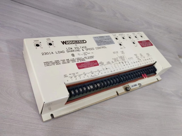
WOODWARD 9905-068
Field Application & Problem Solved
In the field, the biggest challenge with utility paralleling isn’t synchronization—that’s handled by your synchronizer. The real killer is the “power bump” when you close the breaker onto a live utility grid. Without proper load control, you’ll see a massive inrush current that trips your generator breaker, damages the utility interface, or worse, causes a voltage dip that shuts down your critical loads. The 9905-007 solves this by tracking your plant load in real-time and biasing the governor to hold that exact load level the instant the paralleling breaker closes, creating a truly bumpless transfer.
You will typically find this module in cogeneration plants, peak-shaving facilities, and industrial facilities running parallel with the utility grid. It’s the bridge between your generator control system and the utility interconnection requirements. When you’re selling power back to the grid (exporting) or buying power to supplement your generation (importing), the APTL maintains your desired power setpoint regardless of grid frequency variations. You also see these in hospitals and data centers that need zero-power transfer capability—seamlessly switching between utility and generator power without a flicker in the lights.
Its core value is eliminating the mechanical and electrical shock of connecting or disconnecting from the utility. The module tracks the voltage on your load-sharing lines and applies a bias that holds your generators at the exact power level they were producing at the moment of paralleling. From there, you can ramp load up or down at controlled rates (anywhere from 5 seconds to over 2 hours for full load transfer), set base load operation, or run import/export control against the grid. The priority logic is critical—Utility Unload always takes precedence, ensuring you can dump load fast if the utility demands it, while Import/Export mode gives you precise grid-tie power management. The zero-power transfer mode is particularly valuable for closed-transition transfer switches, allowing you to parallel with the utility, match power flow to zero, then open the utility breaker without any disturbance to your load.
Installation & Maintenance Pitfalls (Expert Tips)
Dip Switch Settings Determine Your Ramp Range
The most common field mistake is not checking the S1 dip switch settings before commissioning. The APTL has four dip switches that set the coarse ramp range—from 5-25 seconds up to 30-132 minutes for full load transfer. If you’re expecting a 10-second ramp but the switches are set for the 10-50 minute range, you’ll be waiting an hour for your generator to pick up load. Always verify the S1 switch positions against your application requirements. For emergency backup systems, you want fast ramps (5-30 seconds). For base-loaded cogeneration, slower ramps (5-30 minutes) prevent thermal stress.
The Priority Hierarchy Can Confuse Your Logic
The APTL has a strict priority ladder: Utility Unload at the top, then Import/Export, Unload, Load, Internal Set Point, and External Set Point at the bottom. I’ve seen installations where technicians wired both Import/Export and Utility Unload contacts closed simultaneously, expecting the slower ramp rate, but the control defaults to Import/Export dynamics because Utility Unload only activates its relay after reaching zero power. If you need the fast emergency unload rate, use Utility Unload; if you need controlled grid-tie response, use Import/Export. Never close both unless you understand the handoff logic.
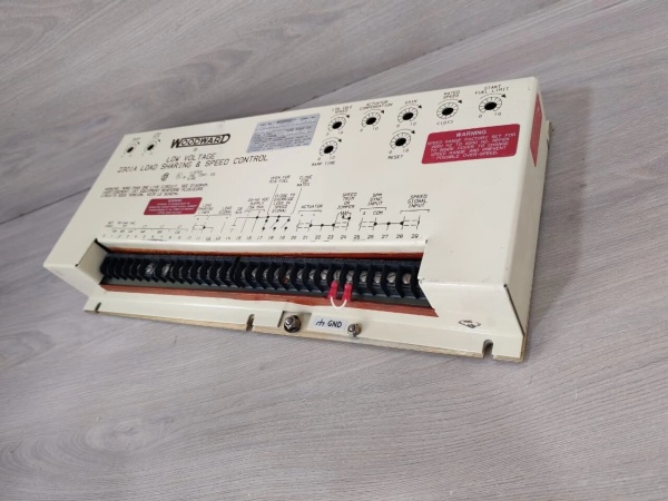
Load Sharing Line Polarity is Critical
The APTL outputs a 0-3 Vdc bias signal to your load-sharing lines (terminals 29 negative, 30 positive). Reverse these connections and your generator will run away—adding load when it should be shedding, or vice versa. This is especially dangerous in Import/Export mode where you’re trying to maintain a specific grid-tie setpoint. Always verify with a voltmeter that positive bias increases generator load. The shielded twisted pair wiring must have the shield grounded at the governor end only to prevent ground loops.
Zero Power Transfer Calibration is Tricky
The Zero Power Transfer setpoint determines when the Utility Unload relay changes state. If you set this too loose, the relay chatters as power oscillates across zero; too tight, and you never achieve the “unloaded” indication needed for your transfer switch logic. During commissioning, use a bidirectional power meter on the utility line and adjust the Zero Power potentiometer until the relay just drops out when power flow is truly zero. This typically requires 2-3 iterations as plant load changes.
Import/Export Low Limit Prevents Reverse Power
In Import/Export mode, the I/E Low Limit potentiometer sets the minimum output voltage—essentially preventing your setpoint from going below zero and creating a reverse power condition. I’ve seen generators motorize and trip on reverse power because this limit was set too low or bypassed. Set the I/E Low Limit for a small positive output (0.1-0.2 Vdc) to ensure some minimum load is always carried by your generators, protecting against utility backfeed.
External Setpoint Loading Requires Range/Level Calibration
If you’re using an external potentiometer or 4-20 mA signal for remote load setpoint, you must calibrate both the Range and Level potentiometers. These interact—changing Range affects Level and vice versa. The standard procedure is: set Range first for your maximum desired load, then trim Level for minimum. If you skip this step, your external setpoint won’t track linearly, and you’ll see “dead zones” where the generator doesn’t respond to setpoint changes.
WOODWARD 9905-068
Technical Deep Dive & Overview
The Woodward 9905-007 is an analog automatic power transfer and load control module from the APTL series, designed to manage the complex dynamics of paralleling generator systems with utility grids. It represents a mature, field-proven architecture that predates digital grid-tie controllers but remains relevant for its reliability and deterministic analog response.
The module operates by monitoring the load-sharing lines of your local generator system—typically 0-6 Vdc signals representing 0-100% load across the plant. When the paralleling breaker closes, the APTL immediately applies a bias voltage to these lines that “freezes” the generators at their current power output


