
Description
Key Technical Specifications
-
Model Number: 9905-002L
-
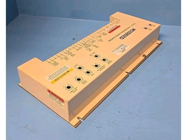
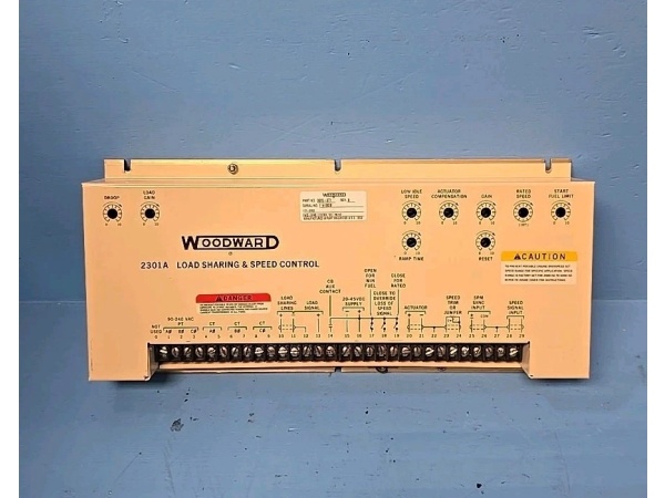
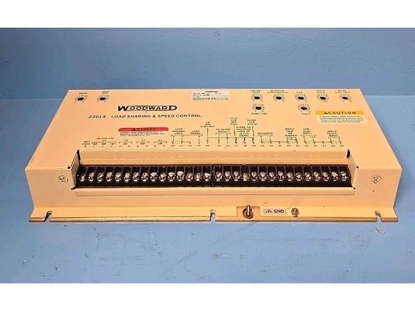
Manufacturer: Woodward
-
Sensing Voltage: 115 VAC or 230 VAC (jumper-selectable)
-
Frequency Range: 50/60 Hz (field-selectable)
-
Power Consumption: 10 W max
-
Phase Window: ±5° electrical (fixed)
-
Slip Frequency: 0.05–0.5 Hz (DIP switch selectable)
-
Speed Bias Output: 0–7 VDC into 5 kΩ, drives 2301A/505 speed reference
-
Breaker Control: Form-C relay, 5 A @ 28 VDC / 120 VAC
-
Voltage Matching: ±1% accuracy via internal comparator
-
Response Time: <50 ms for synchronization adjustments
-
Operating Temperature: –20 °C to +70 °C
-
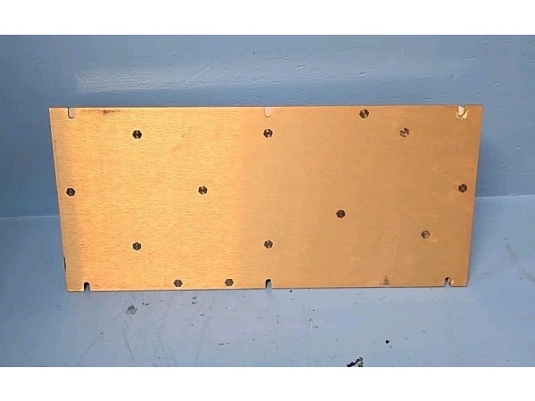
Mounting: 8.5″ × 2″ Euro-card, slides in 2301A chassis or panel-mount

WOODWARD 9905-377
Field Application & Problem Solved
Paralleling a generator by hand is a good way to blow up a breaker or worse—close 120° out of phase and you’ll weld contacts, trip the unit, and possibly damage the shaft. The 9905-002L is Woodward’s analog answer to that problem. It lives in the control panel, watches generator and bus voltage through PT secondaries, calculates slip frequency and phase angle, then gently nudges the governor until the waveforms line up. When slip drops below your setpoint (usually 0.1 Hz) and phase is within ±5°, it outputs a speed bias to hold the engine there and closes the “DEAD BUS” relay to fire the breaker.
Paralleling a generator by hand is a good way to blow up a breaker or worse—close 120° out of phase and you’ll weld contacts, trip the unit, and possibly damage the shaft. The 9905-002L is Woodward’s analog answer to that problem. It lives in the control panel, watches generator and bus voltage through PT secondaries, calculates slip frequency and phase angle, then gently nudges the governor until the waveforms line up. When slip drops below your setpoint (usually 0.1 Hz) and phase is within ±5°, it outputs a speed bias to hold the engine there and closes the “DEAD BUS” relay to fire the breaker.
I use this on 2–5 MW landfill-gas engines and small steam turbines where operators used to stare at a synchroscope and guess when to hit the button. One card replaces the light-bulb scope, the human reaction time, and the inevitable late closures. Real value: it keeps closing even if the operator walks away—no more broken switches or out-of-phase slams that trip the unit offline. You’ll also find it in older 2301A retrofits where the customer wants automatic sync without upgrading to a digital 505.
Installation & Maintenance Pitfalls (Expert Tips)
Verify PT Polarity Before You Start
If the “GEN LEADS BUS” LED is on when the engine is actually slow, your PT polarity is backwards. Swap the wires at the terminal strip—not at the breaker—so you don’t disturb the metering circuits. I’ve seen techs chase this for hours because they checked polarity at the switchgear instead of the card.
If the “GEN LEADS BUS” LED is on when the engine is actually slow, your PT polarity is backwards. Swap the wires at the terminal strip—not at the breaker—so you don’t disturb the metering circuits. I’ve seen techs chase this for hours because they checked polarity at the switchgear instead of the card.
Set Slip Frequency to Match Your Engine
Default is 0.2 Hz, which works for 4-pole gensets. On a 2-pole unit (3600 RPM), dial it down to 0.05 Hz or the breaker will slam at 120° out and trip on instantaneous overcurrent. The DIP switches are on the face—don’t guess, look at the nameplate RPM.
Default is 0.2 Hz, which works for 4-pole gensets. On a 2-pole unit (3600 RPM), dial it down to 0.05 Hz or the breaker will slam at 120° out and trip on instantaneous overcurrent. The DIP switches are on the face—don’t guess, look at the nameplate RPM.
Use Shielded Twisted Pair for PT Leads
Long unshielded runs pick up VFD noise and the card thinks phase is jumping all over. I run #18 shielded twisted pair, ground one end only (at the card), and keep it out of the 480 V bucket. If the “PHASE LOCK” LED flickers, you’ve got noise—add a ferrite bead on the PT leads.
Long unshielded runs pick up VFD noise and the card thinks phase is jumping all over. I run #18 shielded twisted pair, ground one end only (at the card), and keep it out of the 480 V bucket. If the “PHASE LOCK” LED flickers, you’ve got noise—add a ferrite bead on the PT leads.
Interpose the Dead-Bus Relay
The Form-C contact is rated 5 A, but inductive breaker coils will weld it shut over time. I always drive a 24 VDC ice-cube relay first; costs $8 and saves a $300 card replacement when the contactor coil shorts.
The Form-C contact is rated 5 A, but inductive breaker coils will weld it shut over time. I always drive a 24 VDC ice-cube relay first; costs $8 and saves a $300 card replacement when the contactor coil shorts.
Check the Fuse—Not the Card—First
The 9905-002L pulls power from the rack 24 VDC bus through a 1 A fuse. If the LEDs are dead, 90% of the time it’s the fuse, not the card. Keep a strip of Littlefuse 312001 in the toolbox.
The 9905-002L pulls power from the rack 24 VDC bus through a 1 A fuse. If the LEDs are dead, 90% of the time it’s the fuse, not the card. Keep a strip of Littlefuse 312001 in the toolbox.
WOODWARD 9905-377
Technical Deep Dive & Overview
The 9905-002L is an analog phase-locked loop on a single Euro-card. Input transformers drop bus and gen voltage to 12 VAC; zero-cross detectors generate square waves feeding a 4046 phase comparator. The resulting error voltage is filtered to 0–7 VDC speed bias and sent to the 2301A or 505 auxiliary input. A separate window comparator watches slip frequency; when both slip and phase are inside the DIP-selected window, it energizes the dead-bus relay.
The 9905-002L is an analog phase-locked loop on a single Euro-card. Input transformers drop bus and gen voltage to 12 VAC; zero-cross detectors generate square waves feeding a 4046 phase comparator. The resulting error voltage is filtered to 0–7 VDC speed bias and sent to the 2301A or 505 auxiliary input. A separate window comparator watches slip frequency; when both slip and phase are inside the DIP-selected window, it energizes the dead-bus relay.
No microprocessor—everything is op-amps, comparators, and a handful of 4000-series CMOS—so it survives RF storms, never needs firmware, and boots in 100 ms. The “L” revision is an earlier vintage than “N”, with standard acrylic conformal coating and mylar timing capacitors rated for 85 °C. It’ll run fine in clean environments, but if you’re in a paper mill or geothermal site with H₂S, look for the “N” or “P” revision with upgraded coating and 105 °C film caps. Voltage selection is via PCB jumper: move it before you apply power or you’ll cook the input transformers.


